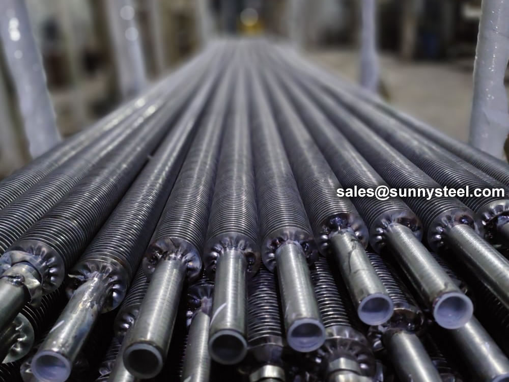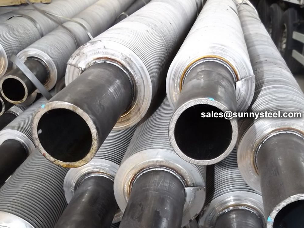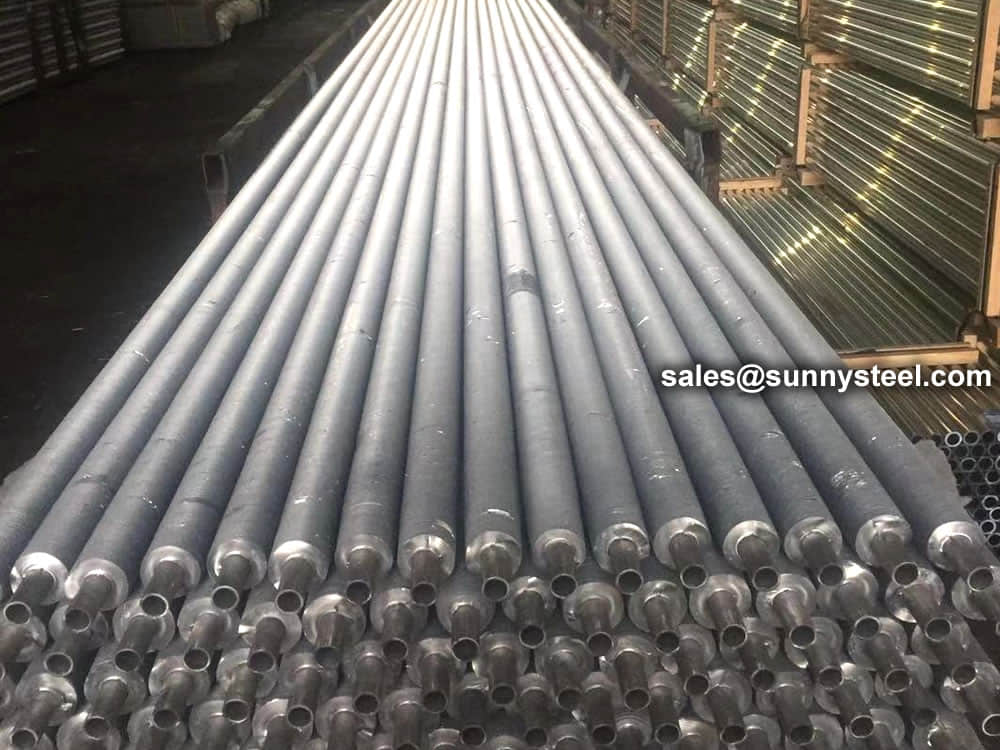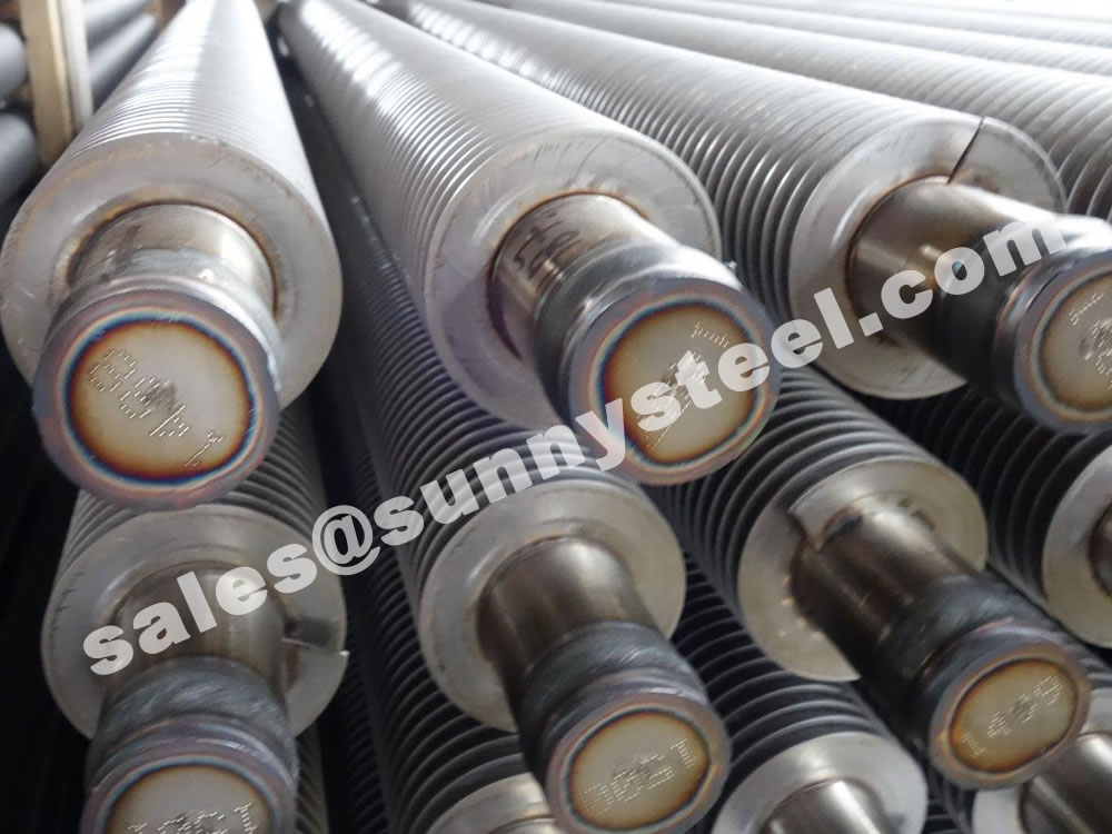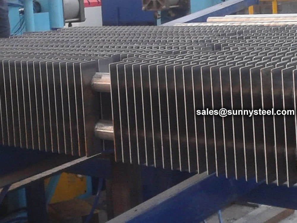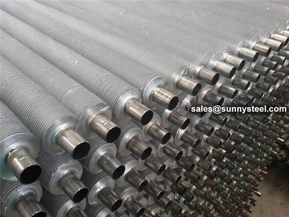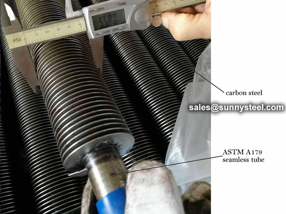
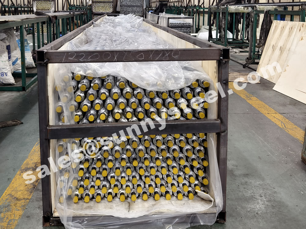
Low Fin tube is a finned tube obtained through plastic cold deformation.
Low Fin (Integral) tubing is a type of extruded tubing that consists of short low fins.
The low fin tube have the advantage of adding surface area to a smooth tube while maintaining the same outside diameter. Low Fin Enhanced tubes can be used in standard shell and tube baffles and tube sheets.
This method of construction is very different from cutting grooves onto the tube as is often done by people who are on the lookout for a shortcut or who don’t know any better.
Download PDF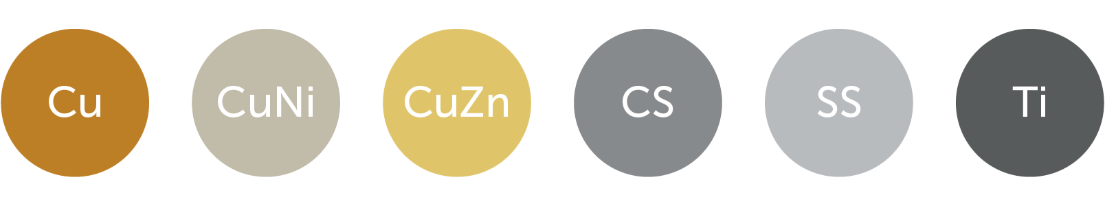
We offer you a broad portfolio of materials and can expand our offering at any time to meet your specific needs regarding thermal conductivity, mechanical properties, or corrosion resistance.
| Material | Standard |
|---|---|
| Carbon Steel | SA 179 / A 179 |
| Carbon Steel | SA 210 / A 210 |
| Carbon Steel | SA 334 / A 334 |
| Stainless Steel | SA 213 / A 213 |
| Duplex Stainless Steel | SA 789 / A 789 |
| Copper & Cu Alloys | SB 111 / B 111 |
| Titanium & Ti Alloys | SB 338 / B 338 |
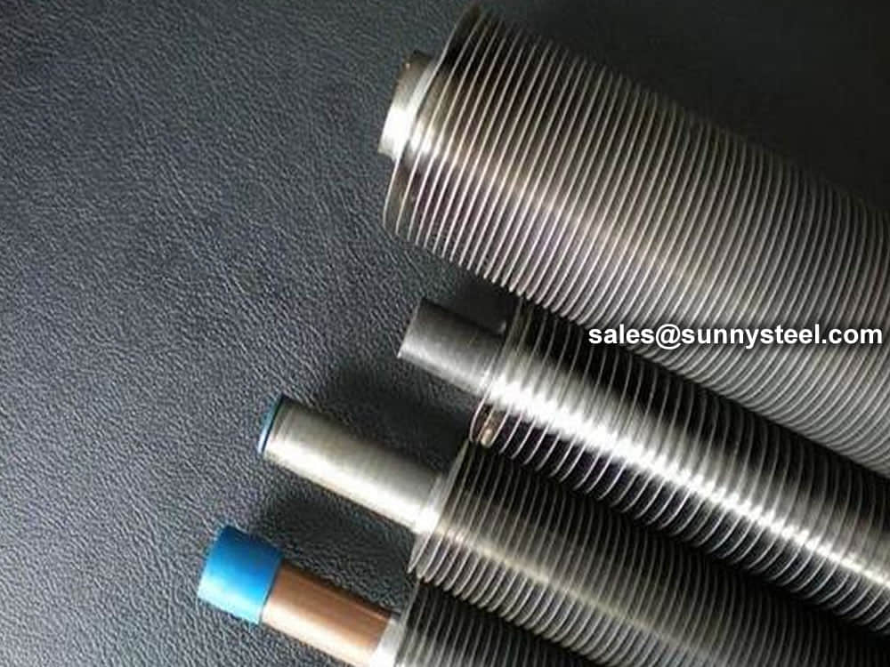
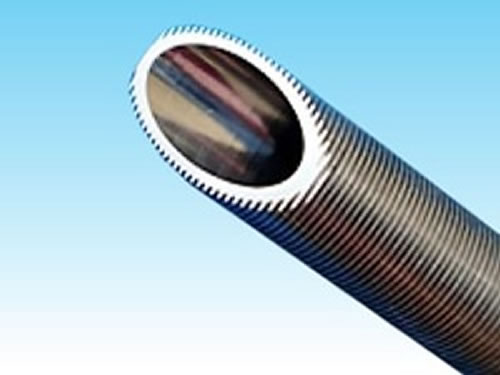
Low-finned tubes solutions are already available in copper, copper-nickel, aluminum, steel, stainless steel, and titanium.
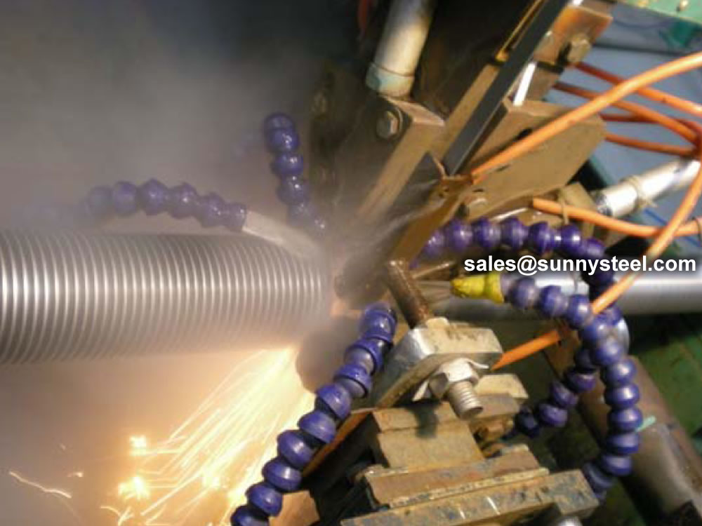
The uses differ, but as far as pipes with an increased outer surface area are concerned, they are all tubes with welded peripheral fins onto steel pipes, also known as high fin tubes. Low finned tubes involve the formation of fins by direct rotational processing of steel pipes, meaning there is no worry of detachment even if later bent. Moreover, they possess excellent durability and anti-vibration properties once put into operation.
Low-finned tubes are used in following fields:
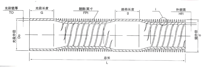
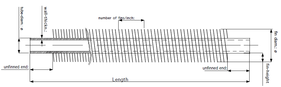
| Description | Size dimension |
|---|---|
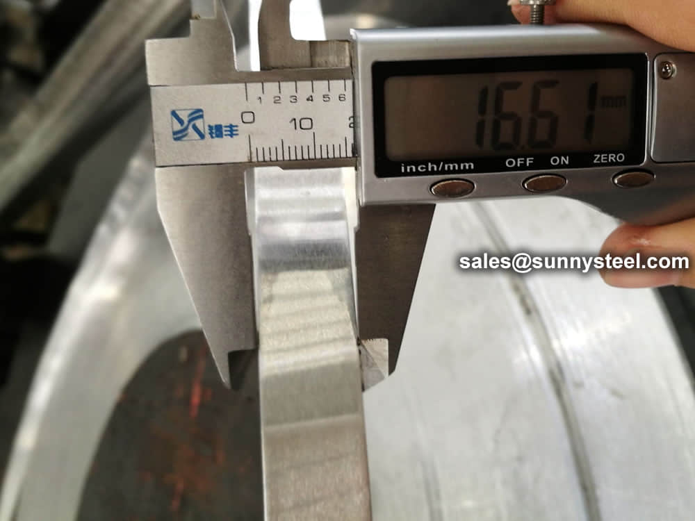
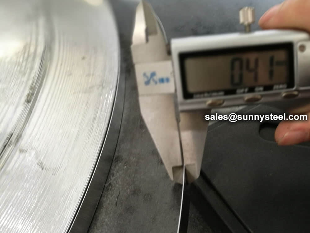
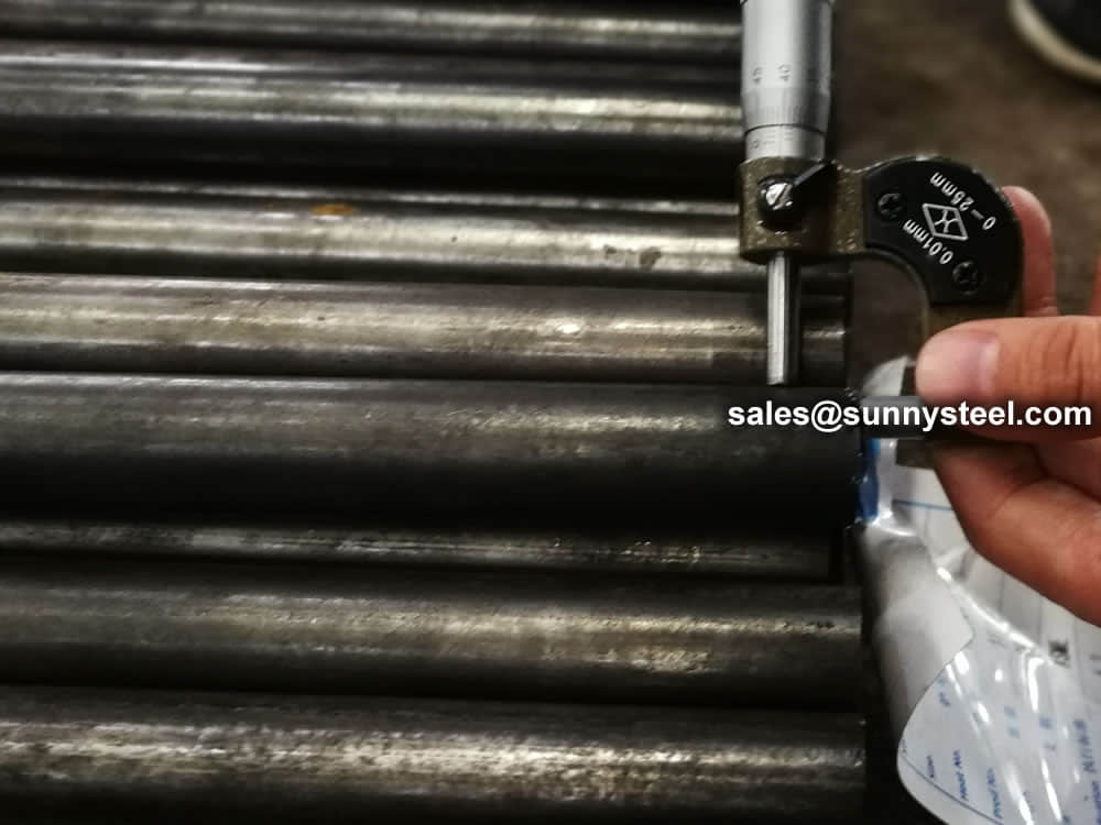
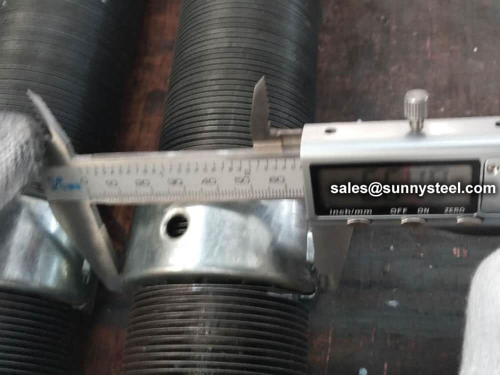
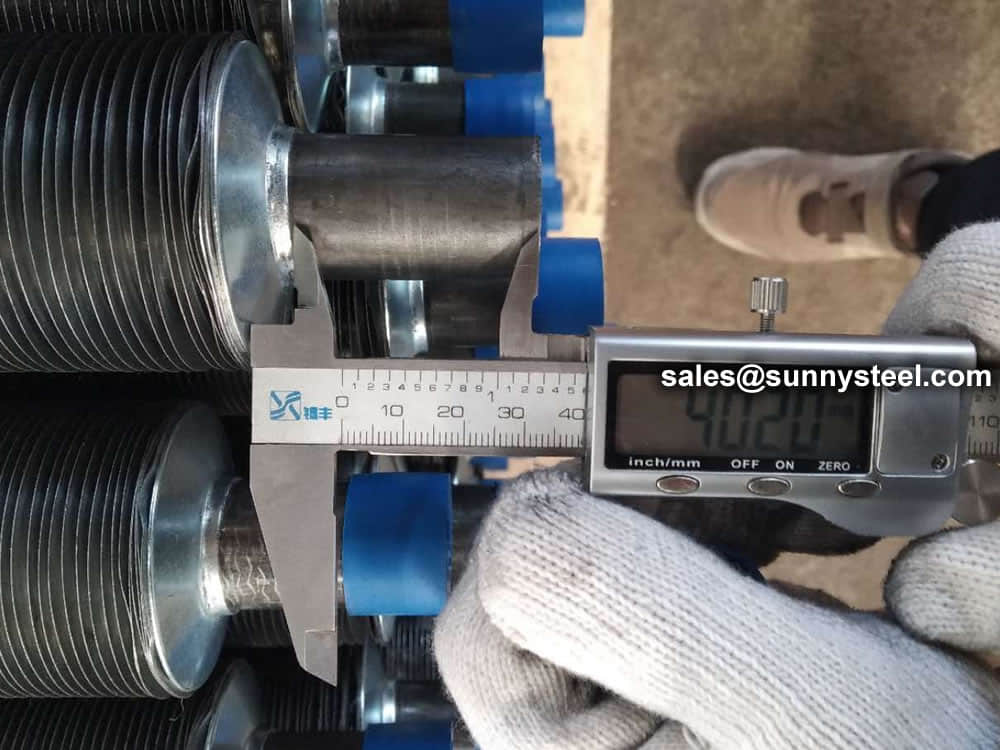
| Tube OD | Min. 12,7mm / Max. 31,75mm |
| Tube thickness (plain section) | Min. 1,245mm / Max. 3,404mm |
| Fin pitch | 19 – 26 – 27 – 28 – 30 – 36 fins per inch |
| Fin height | Max. 1,40mm |
| Tube length | Max. 25000mm |
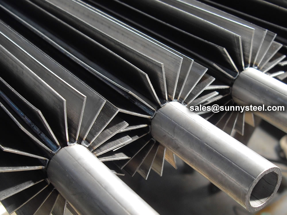
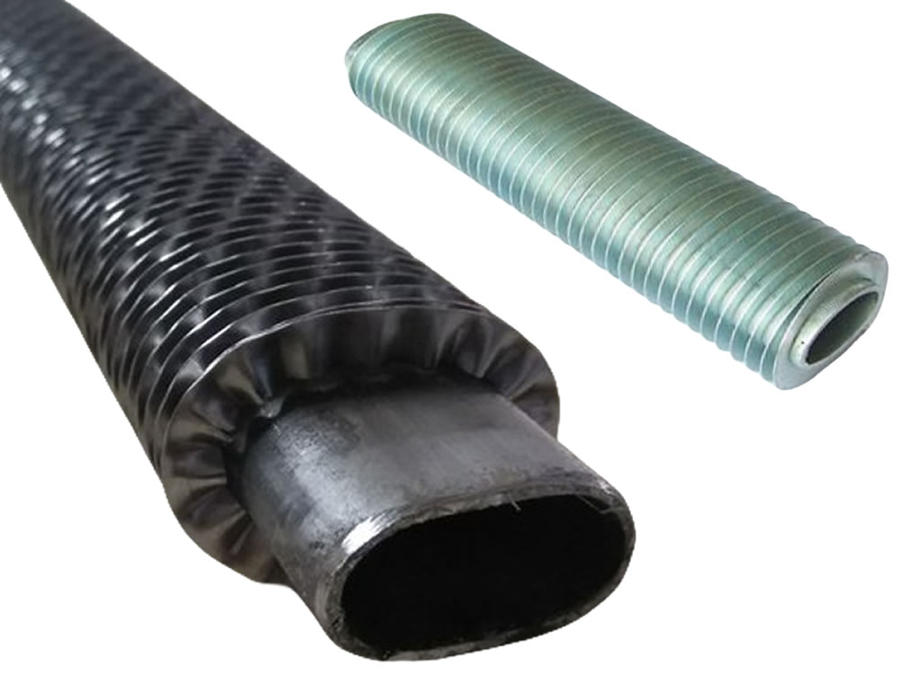
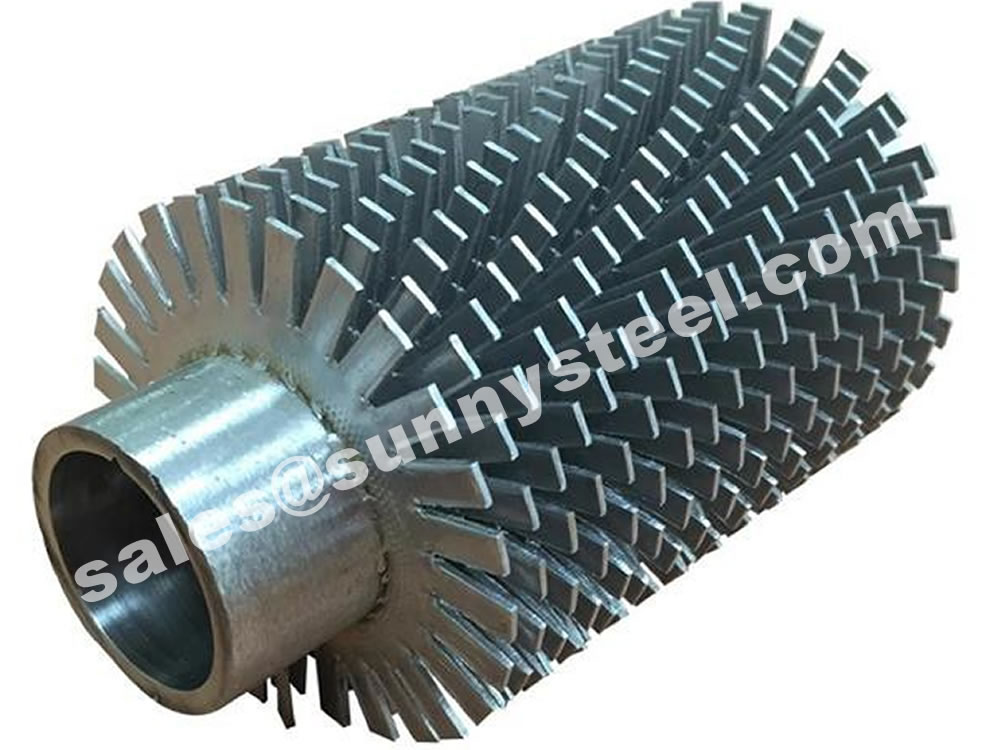
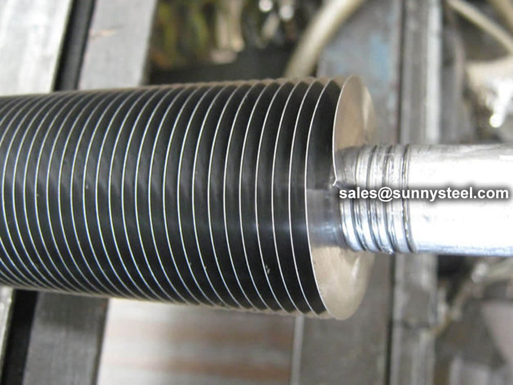
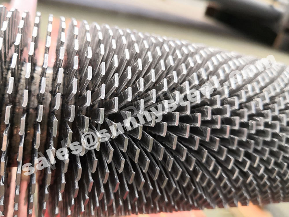
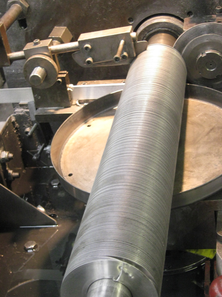
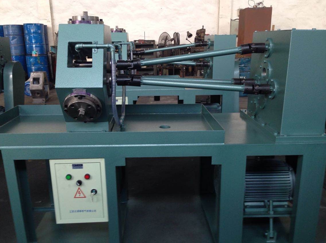
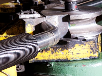
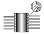
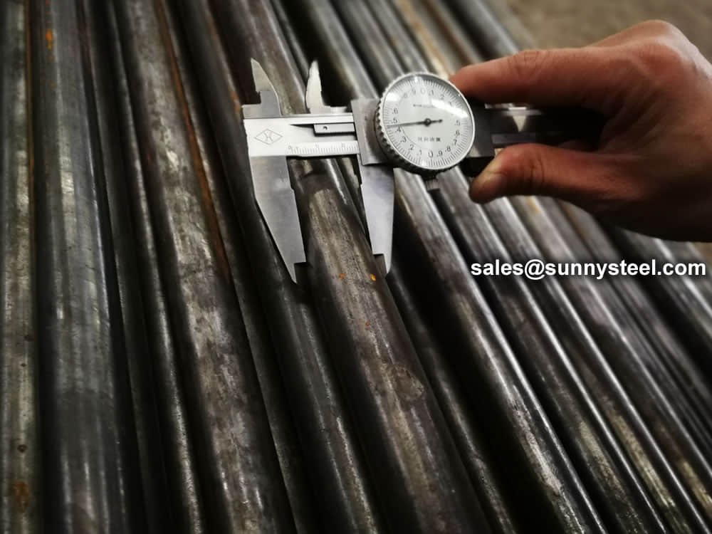
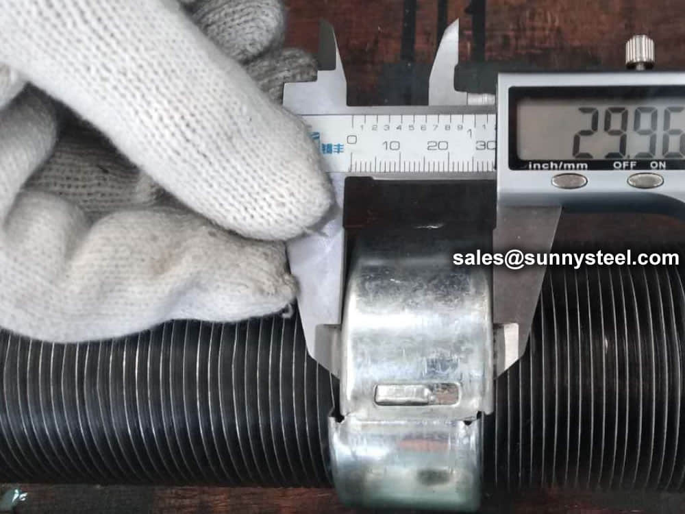
A Low Fin Tube is formed by passing a tube through a set of rollers that form the fins from the parent material of the tube by making it flow in the desired way.
| No. | Standards | Material | Application |
|---|---|---|---|
| 1 | ASTM A498 | Carbon & Carbon alloy | Heat exchanger for Oil refinery and Petrochemical plants |
| 2 | ASTM A1012 | Stainless & Duplex alloy | Condenser and Heat exchanger for Petrochemical & Power plants |
| 3 | ASTM B359 / ASME SB359 | Copper & Copper alloy | Heat exchanger for Petrochemical plants, Condenser & Evaporator for Power plants |
| 4 | ASTM B891 | Titanium & Titanium alloy | Condenser and Heat exchanger for Steam & Nuclear power plants |
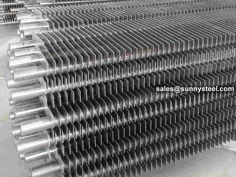
Low Finned Tubes are a type of finned tube that features a continuous external fin, helically wound on the base tube with a relatively low height. The main features of low finned tubes are as follows:
Low finned tubes are commonly used in applications such as heat exchangers, air conditioning systems, and power generation facilities.
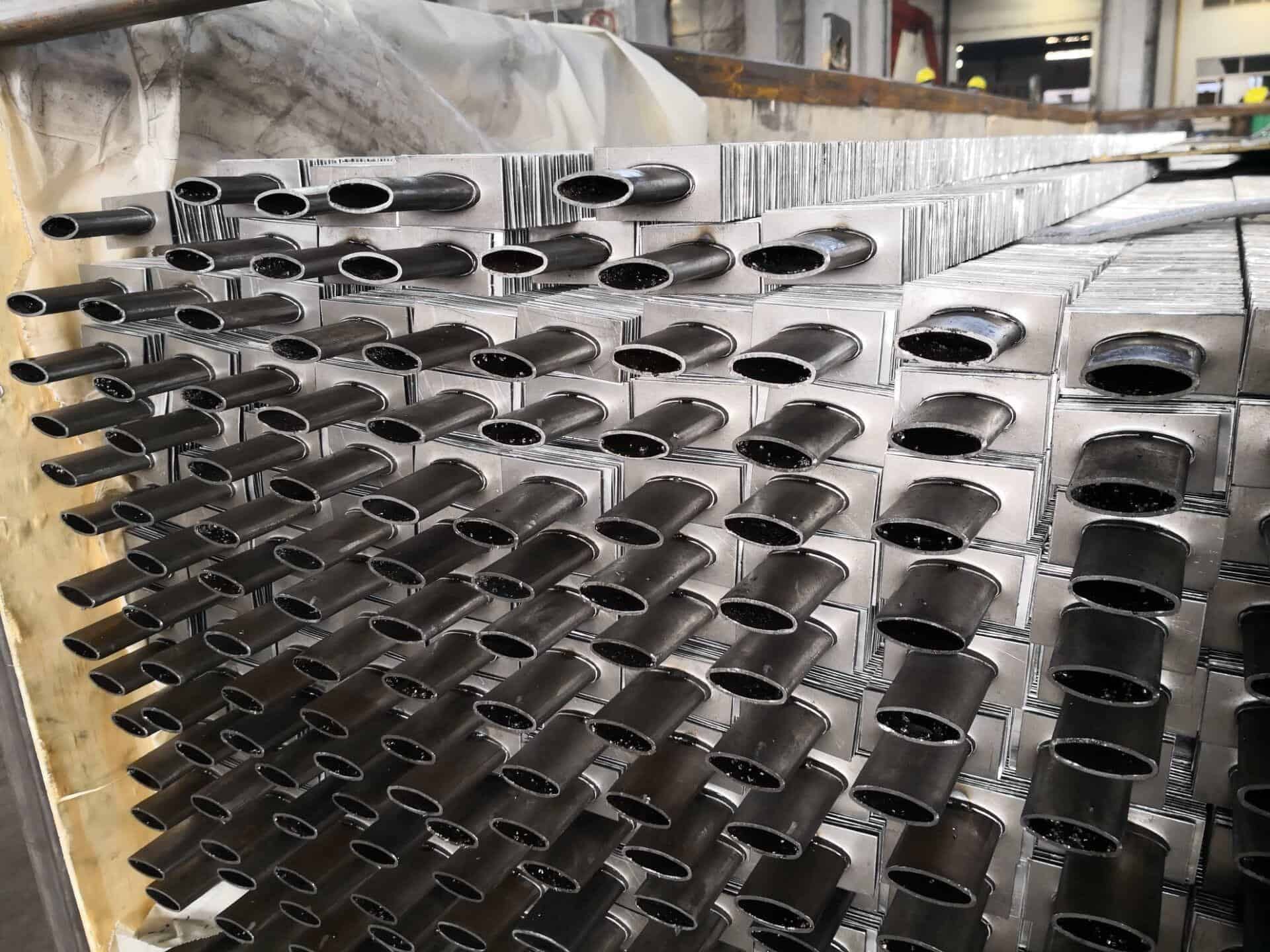
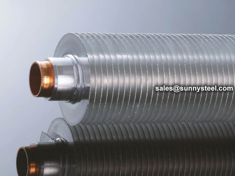
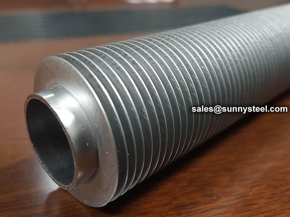
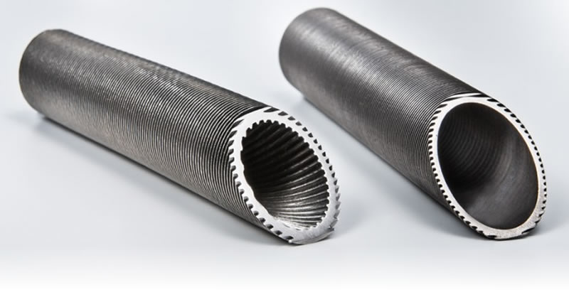
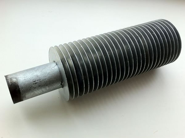
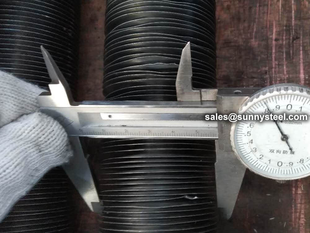
Low-fin (integral) tube is an extruded tube composed of short and low fins, and a high-efficiency heat-exchange tube type in which threaded fins are formed on the outer surface of the heat-exchange tube by rolling. The tube and fin are in the same piece of tube, also known as " N" fin type.
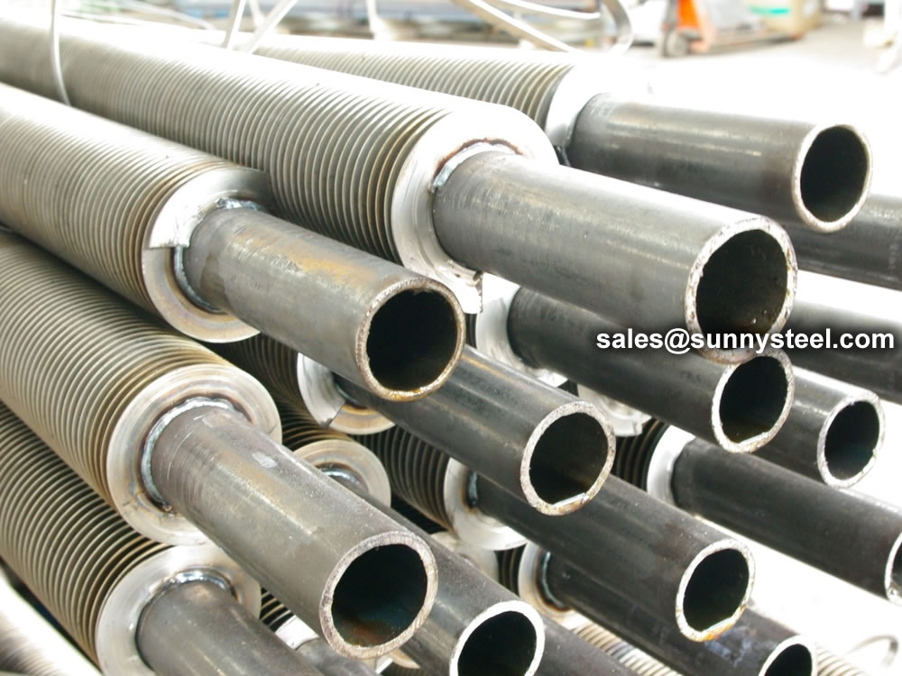
Because Low Finned Tube is an integral tube, there is only one material for the tube and fins
We offer you a wide range of materials and can expand our offering at any time to meet your specific needs in terms of thermal conductivity, mechanical properties or corrosion resistance.
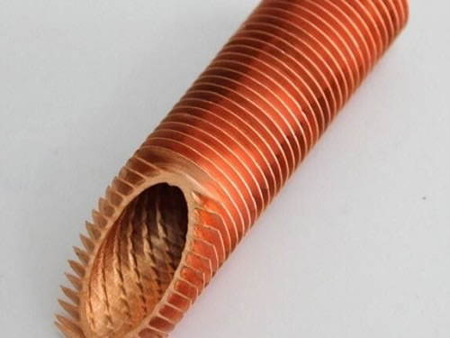
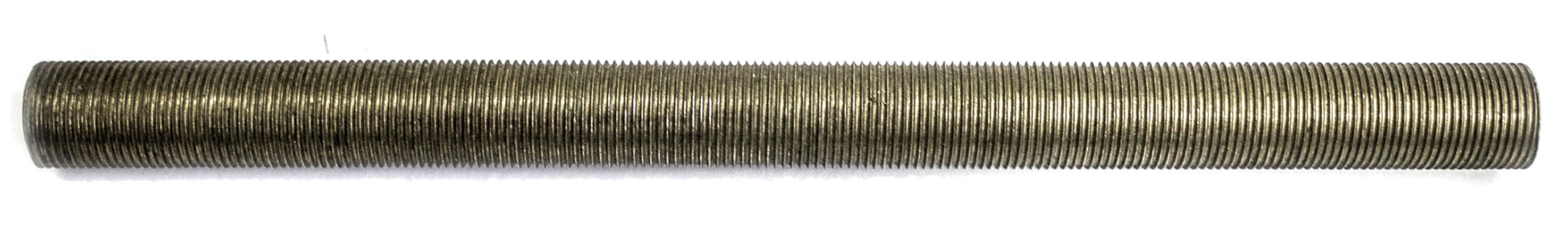
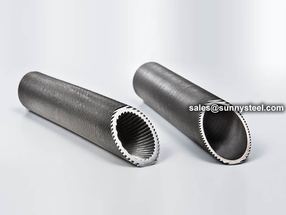
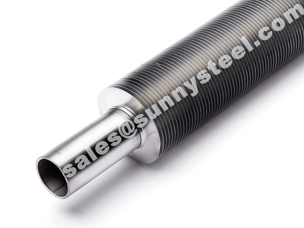
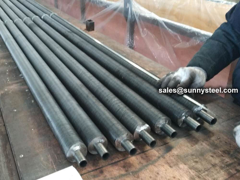
A low fin tube is essentially a single integral tube — made of a singular material — with a smaller fin of about 1/16th of an inch of fin height. The fin is in the tube wall. They are generally used in liquid to liquid or liquid to gas applications such as coolers, condensers, and chillers.
A Low Fin Tube is formed by passing a tube through a set of rollers that form the fins from the parent material of the tube by making it flow in the desired way.
This method of construction is very different from cutting grooves onto the tube as is often done by people who are on the lookout for a shortcut or who don’t know any better.
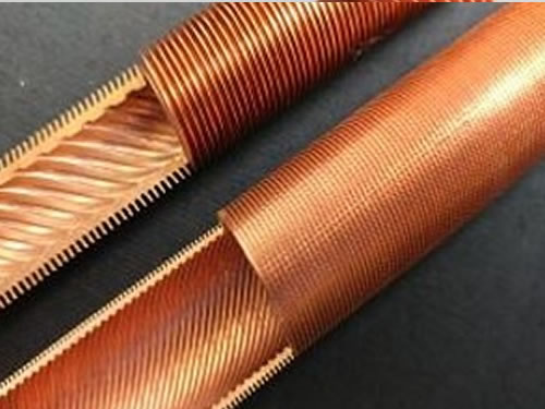
This type of tube can also be internally grooved.
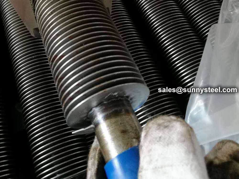
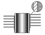
Normally, a condensate forms a static film on a tube impeding further heat transfer. Think of a situation where you pour ice cold water into a tumbler. You’ll find that a condensate film forms on its outer surface. On wiping the film clean, one notices another film form shortly. So every time the film is disrupted, more heat transfer is allowed to take place. This makes a pretty good case for removing condensate film to increase the quantum of heat transfer.
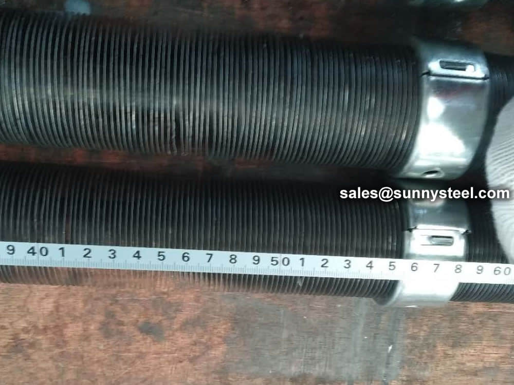
Because a Low Fin Tube has a serrated surface, the condensate forms droplets which fall off intermittently (on account of gravity), repeating the process till the heat transfer objective is met, which wouldn’t be the case with a static film.
This self-cleaning feature makes a Low Fin Tube the automatic tube of choice for condensing applications as its resultant heat transfer capability by preventing static film formation is appreciably higher.
Fins per inch: 19 & 26 FPI
We have designed Low Fin Tubes in Carbon Steel for applications in Ammonia Condensers where copper tubes cannot be used.
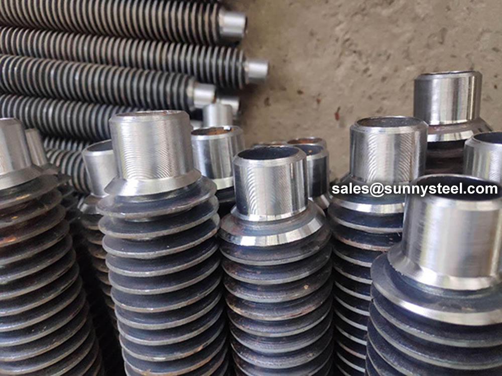
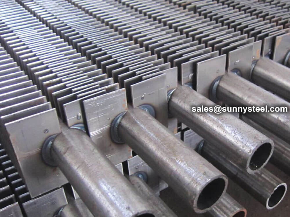
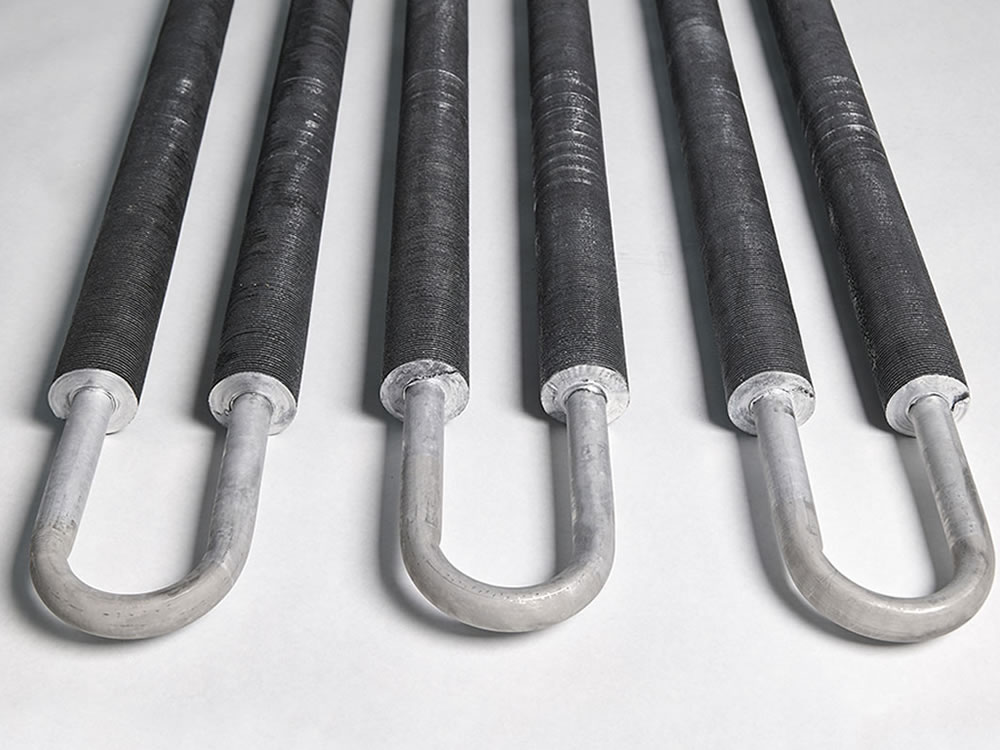
U Bending Low Finned Tubes are high-efficiency U Bending Low Finned Tubes rolled on the outer surface of U Bending heat exchange tubes to form threaded fins. U Bending Low Finned Tubes can be twisted and bent into various shapes. Shaped, square or serpentine configurations to take advantage of more limited spaces.
The fin pitch size of U Bending Low Finned Tubes needs to be determined according to the surface tension of the liquid and the shear force on the liquid film generated by the flow.
U Bending Low Finned Tubes are high-efficiency U Bending Low Finned Tubes rolled on the outer surface of U Bending heat exchange tubes to form threaded fins. U Bending Low Finned Tubes can be twisted and bent into various shapes. Shaped, square or serpentine configuration
The quality of U Bending Low Finned Tubes is assured by hydrostatic or pneumatic testing, eddy current testing and tensile testing to verify the mechanical bond between the inner tube and outer fins
Burr-free, dry and blown on the inside, U Bending Low Finned Tubes are varnished on the outside on both ends.
U Bending Low Finned Tubes mainly rely on the outer ribbing of the tube (ribing coefficient is 2~3) to expand the heat transfer area. Compared with the bare tube, it has a larger surface area with the same consumption of metal materials. Intuitively, it is the first time to strengthen heat transfer, but in essence, the increase of heat transfer area brings about the improvement of heat transfer coefficient. The heat transfer effect, the second strengthens the heat transfer. The main factors affecting the heat transfer enhancement of the ribbed surface are the height of the fin, the thickness of the fin, the distance between the fins and the thermal conductivity of the fin material. In addition, since one side of the heat transfer wall is expanded into a fin surface, the convective heat transfer on the smooth side and the thermal conductivity of the base wall all have a certain influence on the total heat transfer.
U Bending Low Finned Tubes are often used in air coolers, process cooling, lube oil cooling, heat exchangers, steam air heaters, economizers, gas compressor waste incinerators, blast furnaces/rotary furnaces, etc.
Transferring heat from a hot fluid into a colder fluid through a tube wall is the reason many of us use finned tubes.
But you may ask, what is the major advantage of using a finned tube? Why can’t you just use a regular tube to make this transfer? Well you can but the rate will be much slower.
By not using a finned tube the outside surface area is not significantly greater than the inside surface area. Because of that, the fluid with the lowest heat transfer coefficient will dictate the overall heat transfer rate. When the heat transfer coefficient of the fluid inside the tube is several times larger than that of the fluid outside the tube the overall heat transfer rate can be greatly improved by increasing the outside surface area of the tube.
Finned tubes increase outside the surface area. By having a finned tube in place, it increases the overall heat transfer rate. This then decreases the total number of tubes required for a given application which then also reduces overall equipment size and can in the long-run decrease the cost of the project. In many application cases, one finned tube replaces six or more bare tubes at less than 1/3 the cost and 1/4 the volume.
For applications that involve the transfer of heat from a hot fluid to a colder fluid through a tube wall, fin tubes are used. Usually, for an air heat exchanger, where one of the fluids is air or some other gas, the air side heat transfer coefficient will be much lower, so additional heat transfer surface area or a fin tube exchanger is very useful. The overall pattern flow of a finned tube exchanger is often crossflow, however, it can also be parallel flow or counterflow.
Fins are used to increase the effective surface area of heat exchanger tubing. Furthermore, finned tubes are used when the heat transfer coefficient on the outside of the tubes is appreciably lower than that on the inside. In other words, heat transferred from liquid to gas, vapor to gas, such as steam to air heat exchanger, and thermic fluid to air heat exchanger.
The rate at which such heat transfer can occur depends on three factors – [1] the temperature difference between the two fluids; [2] the heat transfer coefficient between each of the fluids and the tube wall; and [3] the surface area to which each fluid is exposed.
A finned tube exchanger typically has tubes with fins attached to the outside. Usually, there will be some liquid flowing through the inside of the tubes and air or some other gas flowing outside the tubes, where the additional heat transfer surface area due to the finned tube increases the heat transfer rate. In a crossflow fin tube exchanger, the fins will typically be radial fins and they’ll either be circular or square in shape.
By not using a finned tube, the outside surface area is not significantly greater than the inside surface area. Because of this, the fluid with the lowest heat transfer coefficient will dictate the overall heat transfer rate. When the heat transfer coefficient of the fluid inside the tube is several times larger than that of the fluid outside the tube, the overall heat transfer rate can be greatly improved by increasing the outside surface area of the tube.
By having a finned tube in place, it increases the overall heat transfer rate. Finned tubes increase the outside surface area. This decreases the total number of tubes required for a given application which then also reduces overall equipment size and can in the long-run decrease the cost of the project.
Finned tube heat exchangers are used in a variety of applications, and more so as industrial heat exchangers. An air heat exchanger like the evaporator coil in an air conditioning unit is typically a fin tube exchanger. Another common fin tube air heat exchanger is the car radiator. The purpose of the car radiator is to cool the hot water in the tubes with the air passing through the crossflow. On the contrary, the air conditioner evaporator coil has the purpose of cooling the air passing through it. The finned tubes that are manufactured at Kainon Boilers, use high grade carbon steel, stainless steel, copper, brass, and aluminum. Our finned tube exchangers are designed to meet the specific duty condition, temperature and pressure of the fluids.
| Type | Description | Base tube | Fin specification (mm) | ||
|---|---|---|---|---|---|
| O.D. (mm) | Fin pitch | Fin height | Fin thick | ||
| Embedded | G-type fin tueb | 16-63 | 2.1-5 | <17 | ~0.4 |
| Extruded | Single metal combined metal | 8-51 | 1.6-10 | <17 | 0.2-0.4 |
| Low fin tube t-type fin tube | 10-38 | 0.6-2 | <1.6 | ~0.3 | |
| Bamboo tube corrugated tube | 16-51 | 8-30 | <2.5 | / | |
| Wound | l/kl/ll type fin tube | 16-63 | 2.1-5 | <17 | ~0.4 |
| String | String fin tube | 25-38 | 2.1-3.5 | <20 | 0.2-0.5 |
| U-type | U-type tube | 16-38 | / | / | / |
| Welding | HF-welding fin tube | 16-219 | 3-25 | 5-30 | 0.8-3 |
| H/HH type fin tube | 25-63 | 8-30 | <200 | 1.5-3.5 | |
| Studed fin tube | 25-219 | 8-30 | 5-35 | φ5-20 | |
Fin tube boilers represent one of a number of pressurized equipment options used to heat water or convert water into steam under controlled conditions. As in a water tube boiler, water passes through boiler tubes while combustion gases remain in the shell side, passing over the tube surfaces.
Our factory is equipped with professional technical research and design personnel who can provide product optimization design and services.
Quality is the foundation of an enterprise, the company adopts the most advanced production equipment and the best management and technical personnel in the same industry, constantly improves the product technology, strictly controls every step of the processing process, and strives to meet the fierce market competition with first-class quality products, so as to keep the company at the forefront of the industry forever.
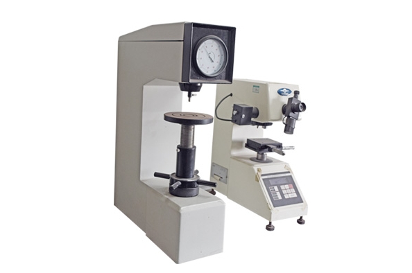
Testing instrument
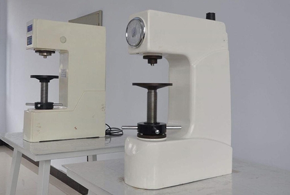
Hardness tester
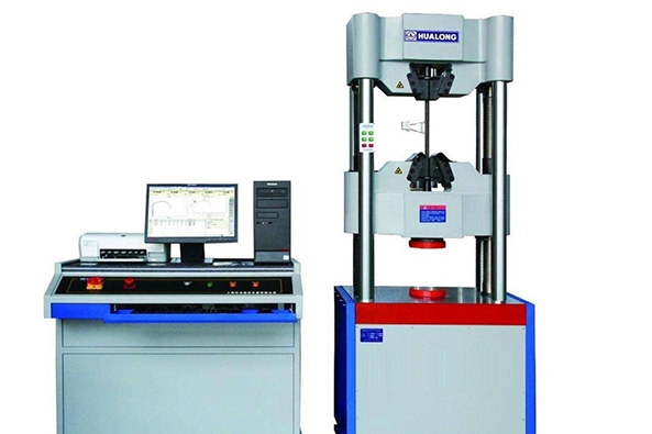
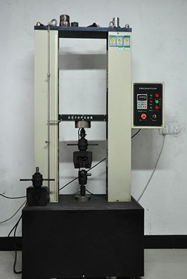
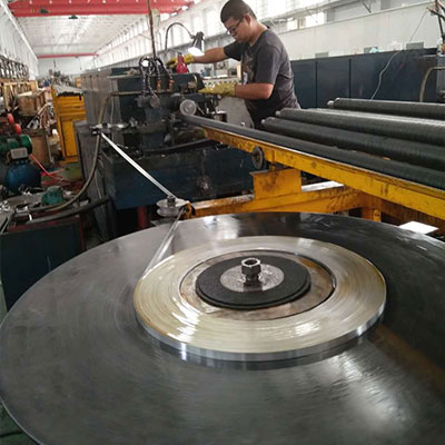
Drawing Machine
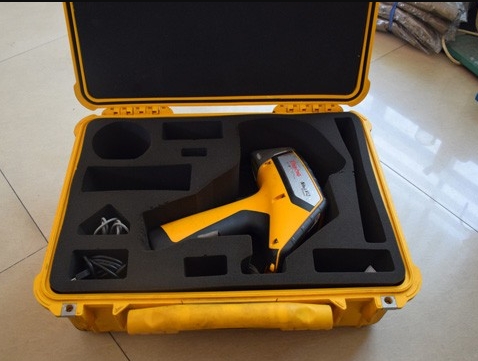
Component analyzer
Aluminium KL finned tube
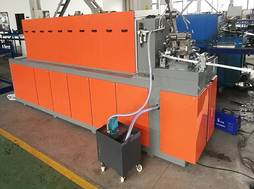
L LL KL G production line
Production equipments
Extrusion equipment
Fin tube bending
Specific classification of finned tubes, there are lot of types of finned tubes, meanwhile also lot of new species comes up.
And so on.
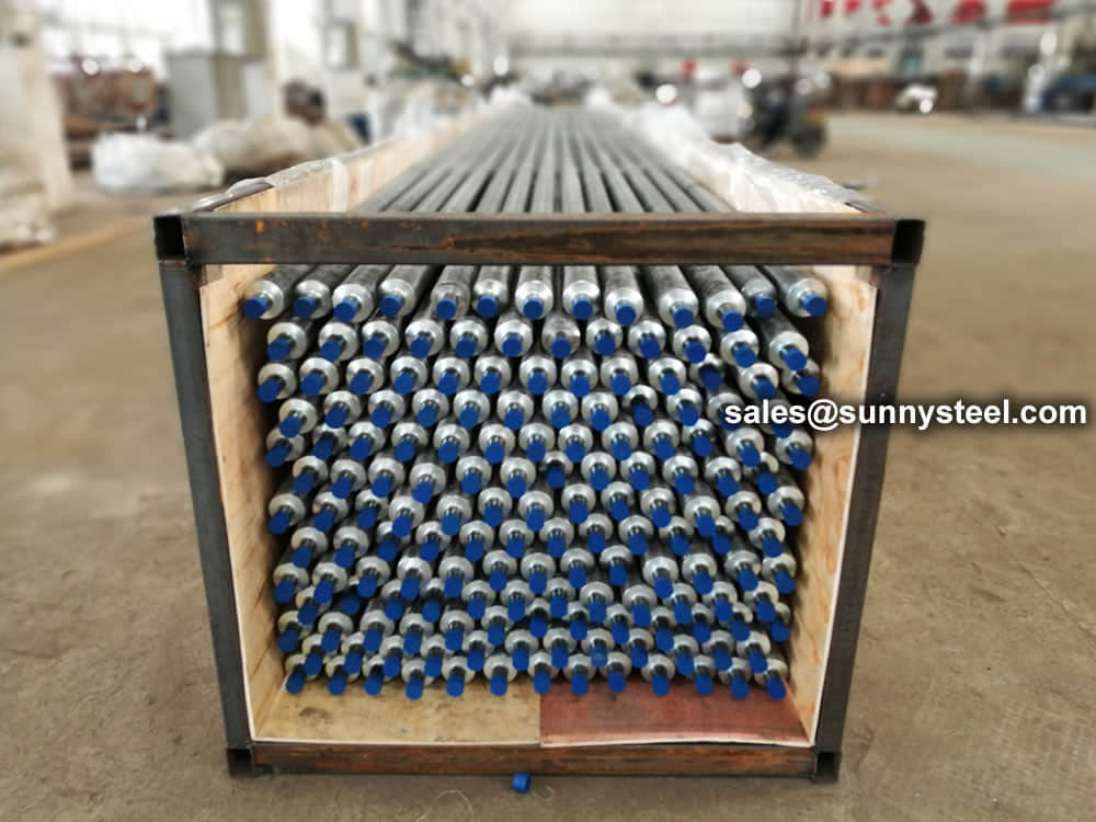
The material certificate including all the tests can be provided, and also with EN10204 3.1standard.
Отопительные трубы с ребрами обеспечивают хорошую теплопередачу, благодаря абсолютно жесткой посадке плоского ребра на внутренней трубе. Наши отопительные трубы с ребрами применяются везде, где особые условия монтажа требуют использования необычных решений, например, в фасадных системах отопления, на многоярусных складах, в теплицах, при защите стеклянных куполов от запотевания и т.д., также трубы используются для отопления жилых, промышленных и складских помещений. Имеют документированную высокую степень теплоотдачи.
Ребристые трубы монтируются при помощи стандартных фитингов, либо под сварку по желанию Заказчика.
Мы изготавливаем два типоразмера ребристой трубы :
Ду32 и Ду40.
Длину трубы определяет Заказчик.
Покрытие трубы:
-грунт
-порошковая окраска
-горячий цинк.
По ценам и срокам изготовления вы можете узнать, позвонив по телефону
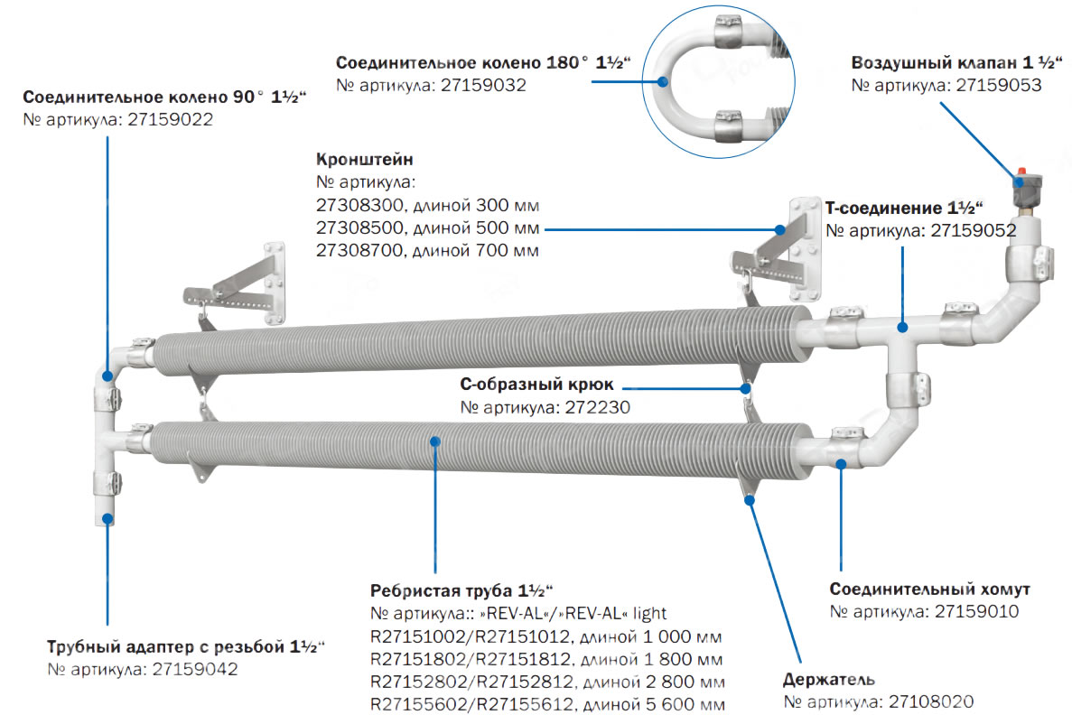
Ребристая труба для отопления на свинокомплексах и птицефабриках
It is fabricated with a batch of single fins that were processed by the punch press and then manually or mechanically, with a certain distance (wingspan) on the base tube.
This is the earliest fin tube fabrication with low cost and simple production process/ technology, easy to maintain. Divides into manual set and mechanical set. Manual set uses a tool that relies on the power of man to press the fins one by one. This method is limited by the pressure of the fin, so it is easy to get loose. The machine – set fin is carried on the wing piece machine. Due to the mechanical impact or liquid pressure, the pressure of the fin is high, so it can be used in a larger volume. The bonding strength between fin and tube is high and not easy to loosen. Mechanical transmission has high productivity, but the noise is large, the safety is poor, and the working conditions of the workers are not good. Although the hydraulic transmission does not have the above problem, but the equipment price is more expensive, the technical requirement to use maintenance personnel is higher, its productivity is also lower.
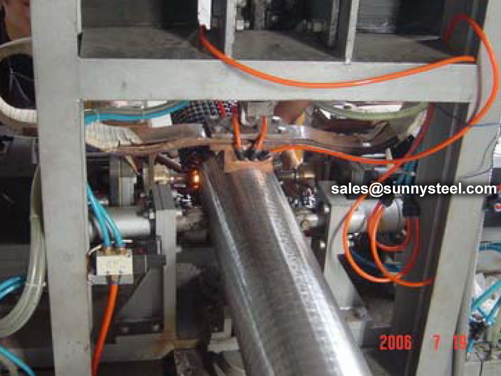
Currently HF Fin Tube is one of the most widely used helical fin tubes, you can see it as waste heat recovery in power, metallurgy, concrete, oil and gas, petrochemical, etc. When winding the steel strip around steel tube, the use of high frequency current skin effect and proximity effect on steel strip and steel pipe surface heating, until the plastic state or melt, the coil steel belt must be under pressure to complete welding. Comparing with embedded type and spot welding spiral crimped type, it is more advanced either on fin tube quality or production efficiency or automation degree.
The extruded fin is formed from an outer aluminum tube with a large wall thickness (muff), which is aligned over an inner base tube. The two tubes are pushed through three arbors with rotating discs that literally squeeze or extrude the aluminum fins up and out of the muff material in a spiral shape in one operation. Comparing with welding fin tube, dr extruded fin has higher production efficiency with low cost on material and high heat transfer. At present, it divides into copper or aluminum single metal fin tube and bi-metal composited fin tube.
Fin tube manufacturers produce a wide range of fin tubes. They are used in heat exchangers (air, water and chemically cooled) for various industries such as petroleum, petrochemical, steel, power generation and many more.
Corrosion protection processes are performed during fin tube manufacturing and the material used is corrosion resistant. Some fin tube types are:
Helical high finned tubes are used to repair air-cooled heat exchangers and are available in 5 variations
| Type | Photo | Descriptions | Properties |
|---|---|---|---|
| "KL" fin tubes | 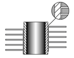 |
After application the fin foot is knurled into the corresponding knurling on the base tube thereby enhancing the bond between the fin and tube resulting in improved heat transfer characteristics. Max. operating. temp. 260ºC | Max working temperature – 260 °C (500 °F) Atmospheric corrosion resistance – acceptable Mechanical resistance – acceptable Fin material – aluminum, copper |
| "G" fin tubes |
|
Fin strip is wound & embedded on a groove and securely locked by closing the groove with the base tube metal. This ensures maximum heat transfer at high temperatures. Max. operating temp. 450ºC |
Max working temperature – 400 °C (752 °F) Atmospheric corrosion resistance – poor Mechanical resistance – acceptable Fin material – aluminum, copper, carbon steel |
| "LL" fin tubes |
|
Manufactured in the same way as the ‘L’ fin type except that the fin foot is overlapped to completely enclose the base tube thereby giving excellent corrosion resistance. This type of tube is often used as an alternative to the more expensive extruded type fin in corrosive environments. Max. operating. temp. 180ºC | Max working temperature – 180 °C (356 °F) Atmospheric corrosion resistance – acceptable Mechanical resistance – poor Fin material – aluminum, copper |
| “L” fin tubes | 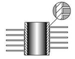
|
The strip material is subjected to controlled deformation under tension giving the optimum contact pressure of the foot of the fin onto the base tube thus maximizing the heat transfer properties. The foot of the fin considerably enhances the corrosion protection of the base tube. Max. operating. temp. 150ºC | Max working temperature – 150 °C (302 °F) Atmospheric corrosion resistance – acceptable Mechanical resistance – poor Fin material – aluminum, copper |
| Extruded fin tubes | 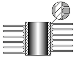
|
This fin type is formed from a bi-metallic tube consisting of an aluminium outer tube and an inner tube of almost any material. The fin is formed by rolling material from the outside of the exterior tube to give an integral fin with excellent heat transfer properties and longevity. Extruded fin offers excellent corrosion protection of the base tube. Max. operating. temp. 280ºC. | Max working temperature – 285 °C (545 °F) Atmospheric corrosion resistance – excellent Mechanical resistance – excellent Fin material – aluminum |
Fin foot is pre-formed into an LL shape (overlapped LL) and applied to base tube under tension.
However, foot is pre-shaped to give overlap of one foot onto another, thereby improving base tube protection and thermal contact area Fin materials: Aluminum Base tube materials: Any metallic material.
The smooth flat fins perpendicular to the tube surface give rise to very low resistance to air /gas flow and ensure that fouling is kept to a minimum. The foot of the fin is in contact with base tube and provides a complete sheathing over the finned length.
The Overlapped “L” fin design has interlocking fins that are wound together to prevent movement and separation. The fin protects the entire tubes, so the designation works well for the applications where corrosion is a factor.This type of finned tube is often used as an alternative to the more expensive extruded type fin in corrosive environments.
Fin tubes are a type of heat exchanger that is used in many different industries. These tubes have a finned surface, which increases their surface area and allows them to transfer heat more efficiently. This makes them ideal for applications where high heat transfer rates are required, such as in power plants and refrigeration systems.
Fin tubes are made from a variety of materials, including copper, aluminum, and stainless steel. They are available in a range of sizes and shapes and can be customized to meet the specific needs of each application.
One of the key benefits of fin tubes is their ability to operate efficiently at high temperatures and pressures. This makes them suitable for use in a wide range of applications, including air conditioning, heat exchangers, and radiators.
In addition to their high thermal performance, fin tubes are also durable and long-lasting. They are resistant to corrosion and can withstand the harsh environments often found in industrial settings. This makes them a cost-effective solution for many different industries.
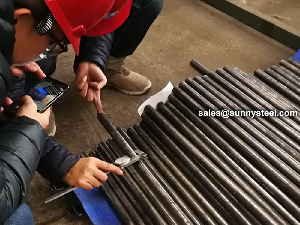
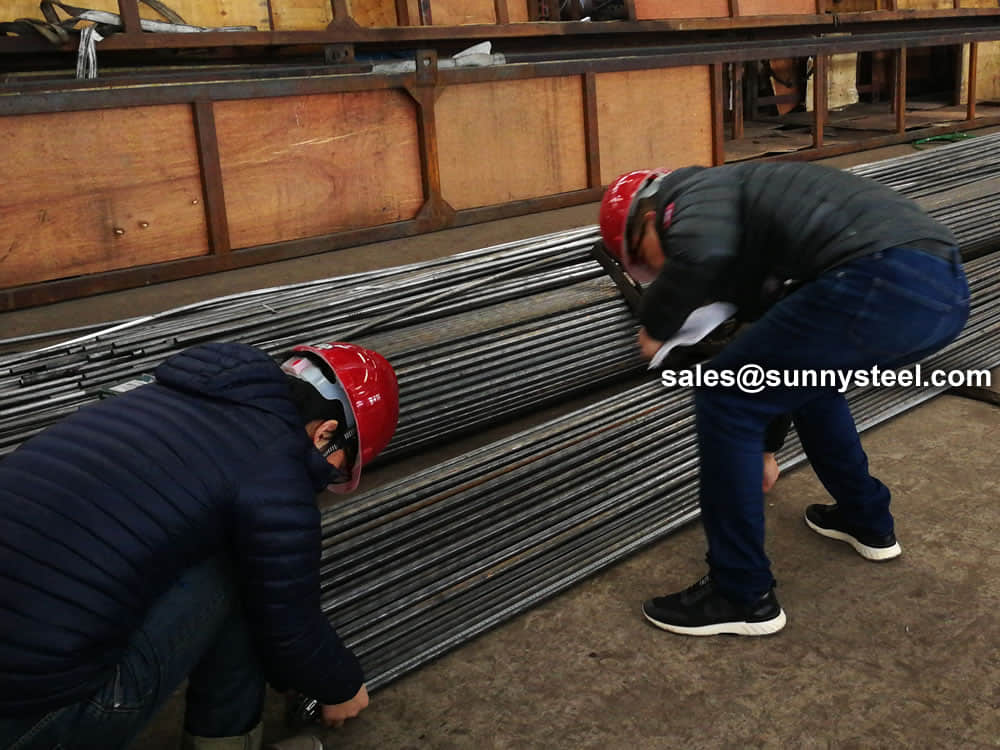
The first actual inspection work on the fin tube heat exchanger is the raw materials inspection. Based on the ASME Code, providing material test reports for fin tube heat exchanger plates is mandatory. For other components, the marking inspection will be enough.

The Finned Tube is exposed to the outside to prevent rainwater from falling, try to keep it dry, and it should not be too close to the ground to prevent the irrigation in the greenhouse from corroding the finned tube. After the maintenance of the finned tube, the service life of the finned tube will be greatly increased.


We are a pretty proactive bunch. So, while we do charge a small fee per design to cover our costs, we absorb these costs when it is for a regular customer or where we are working jointly on a project. We also refund the fees in case it is followed by an order.
Absolutely, we can.
Applied Fin Tube is made with strip wrapped under tension around the base of the tube. Fins are welded to the base tube at the strip ends.
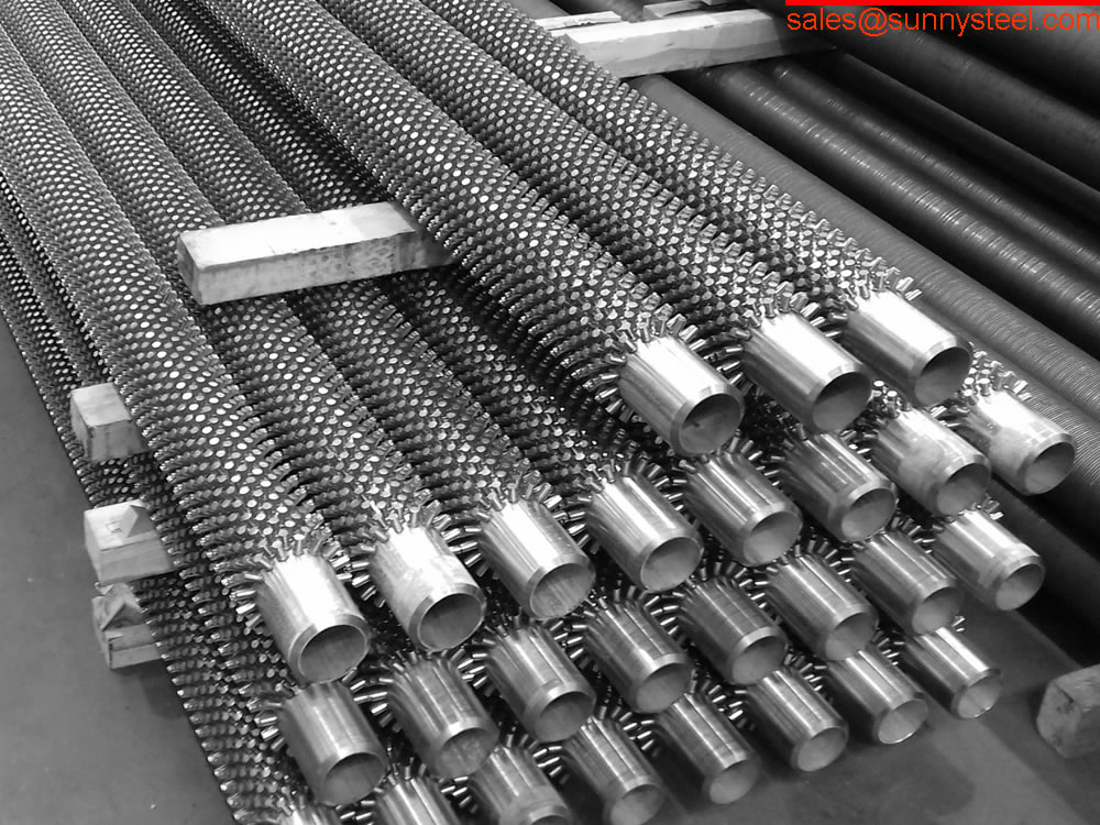
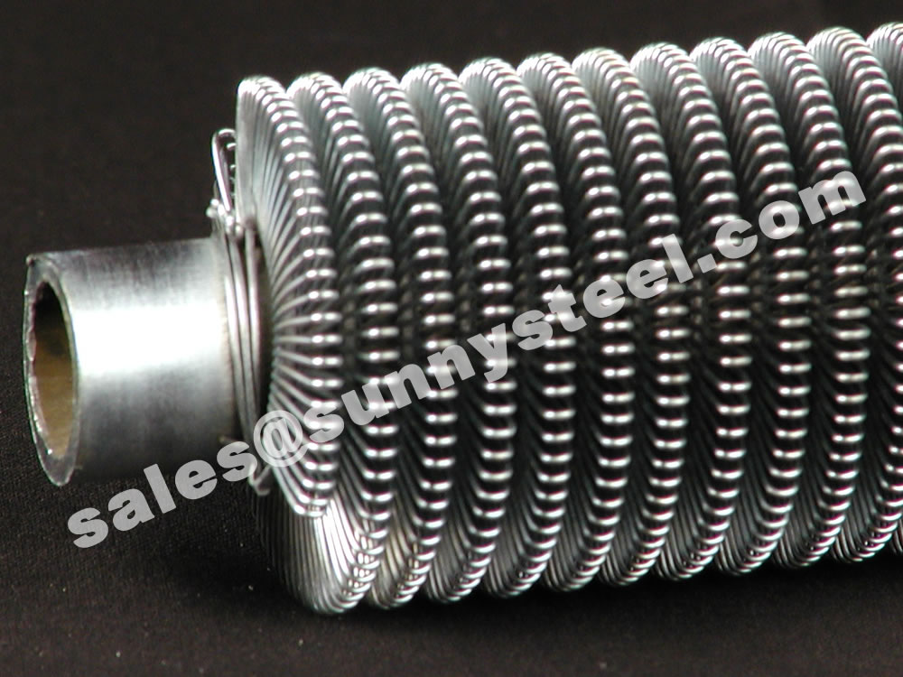
Pin Fin tubes are made from wire. Being cylindrical, wire has a larger area per unit of weight than the strip used in L type fin tubes. Also, due to the looped nature of the wire, less material is put on the tube than in the case of L fins. Consequently, the surface area of fins per meter of tubes is also less. However due to the superior turbulence created by the looped wire the actual heat transfer per meter of tube is significantly higher than in the case of L Type Fin Tubes. All of this together contributes to the weight differential between wire wound fin tubes and L Type Fin Tubes. In the case of similar metals, it is weighing half and in the case of Aluminium L fin vs. Steel wire fin they weigh about the same. The higher performance S5 pin fin tubes have an airside heat transfer performance per meter of tube that is 250% of the L type fin tubes.
Yes. A lot of our customer choose to supply their own pipes or tubes, however, a lot of customers ask us to supply them and we are happy to accommodate! We stock various sizes and if we don’t have what you need we can bring it in from one of our many suppliers. If you would like us to include the pipe or tube material in your order, please indicate that when you request a QUOTE.
A continuous helical fin is attached to the base tube by high frequency electric resistance welding in order to give an efficient and thermally reliable bond. Fins can be either solid or serrated (segmented). The weld produced in this process is a true forge, blacksmith weld. This type of weld is comprised of a fusion between two portions of parent metal without the introduction of a filler material. The weld is simply produced by heating the interfaces to be joined to a plastic state and applying pressure.
Used in boilers, furnaces and fired heaters for efficient heat recovery.
The main uses for high frequency welded finned tubes are in the heat recovery associated with boilers for power generation and in furnace applications for the petrochemical industry.
Our finning machines are equipped with online single or duplex cold bending equipment that can manipulate both ends of tubes in a single operation, thus ensuring exact alignment of the ends.
We do not. Our market lends itself to customer designed products, each special in itself. The number of combinations of diameter, overall length, materials and fin specs are too vast. Sunny Steel builds each finned product to each customers needs.
Finned tubes are the main components of heat exchangers. They are a series of tubes where fins have been added on the outside to increase the contact area with the outside fluid, to exchange heat and between the fluid inside the tube and the fluid outside the tube. Finned tubes are elongated aluminium cladded carbon steel flat tubes with brazed aluminium fins.
The rate at which such heat transfer can occur depends on three factors:
For any kind of information and request do not hesitate to contact our team, Sunny Steel is at your complete disposal.
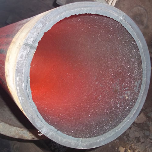
Ceramic lined pipe is made through self-propagating high-temperature synthesis (SHS) technique.
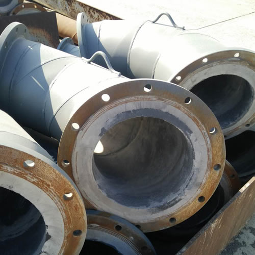
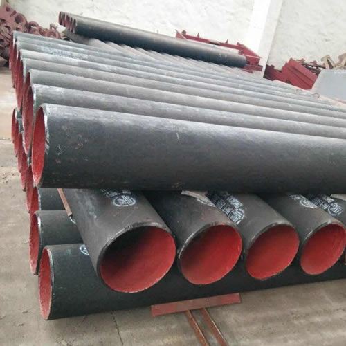
Cast basalt lined steel pipe is composed by lined with cast basalt pipe, outside steel pipe and cement mortar filling between the two layers.
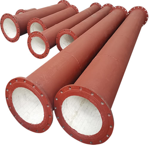
Ceramic tile lined pipes have very uniform coating of specially formulated ceramic material that is affixed to the inner of the pipe.
The material of the rare earth alloy wear-resistant pipe is ZG40CrMnMoNiSiRe, which is also the grade of rare earth alloy steel.
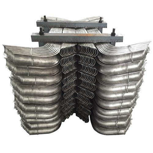
Tubes Erosion Shields are used to protect boiler tubing from the highly erosive effects of high temperatures and pressures thereby greatly extending tube life.
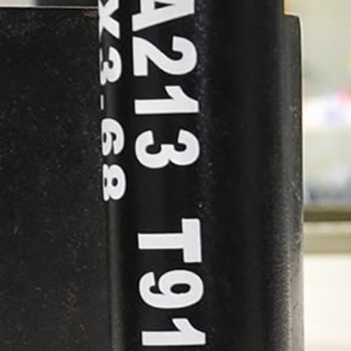
The ASTM A213 T91 seamless tubes are primarily used for boiler, superheater, and heat-exchanger.

When you partner with Sunny Steel, you can stop worrying about meeting deadlines thanks to our responsive and timely service. You'll also say goodbye to unnecessary shopping around. Instead, you'll get white glove service from an expert who understands your needs and can get you the materials you need quickly.