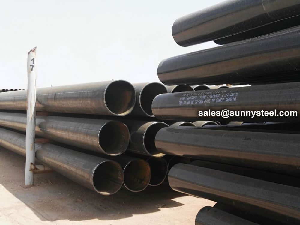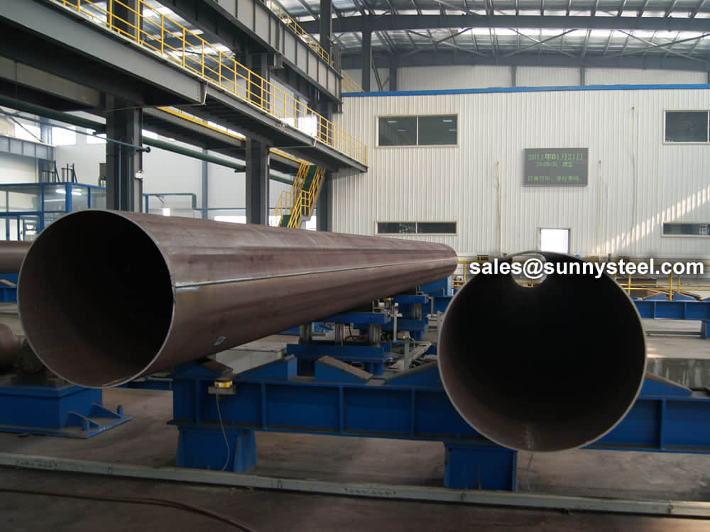
DSAW Pipe
Double Submerged Arc Welded (DSAW) pipes for reliable and strong construction.
In High Frequency Induction (HFI) Welded Pipe production process, hot rolled steel coils are fed with a high capacity accumulator in order to achieve continuous welding.
HIGH-FREQUENCY WELDING is a welding process in which the heat source used to melt the joining surfaces is obtained from high-frequency (HF) alternating current (ac) resistance heating.
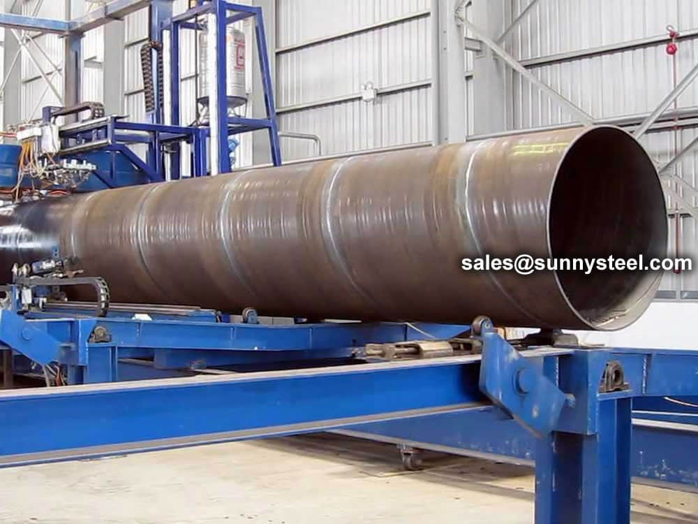
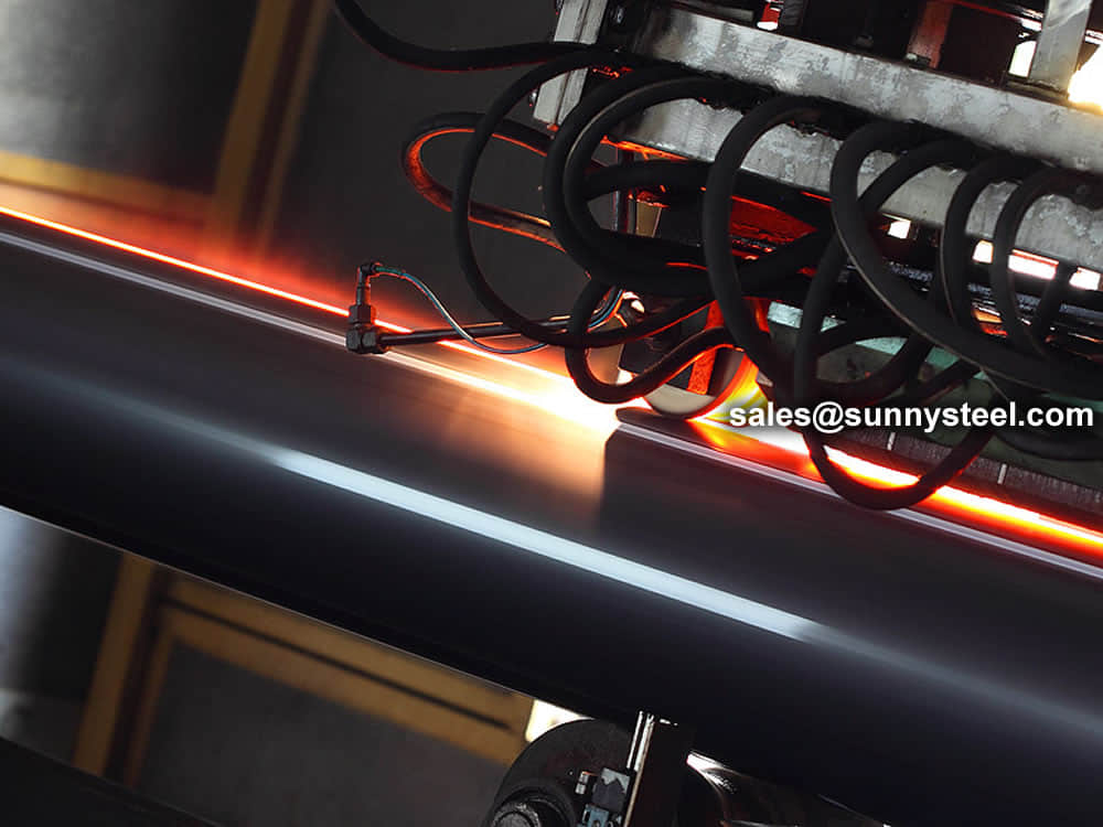
The high-frequency induction (HFI) resistance pressure welding technique for longitudinal welding. The endless strip passes through rolling stands where it is shaped to an open pipe, which runs through a high-frequency inductor consisting of a metal coil with single or multiple windings. As a result, high-frequency ring current is induced into the pipe that closes preferably at the strip edges which converge in the welding point. The temperature required for welding is generated by resistance heating of a narrow zone along the strip edges.
The heated strip edges are squeezed together by pressure rollers, resulting in a homogeneous longitudinal weld without any filler metals. The flash generated on the inside and outside surfaces during welding is scraped off to the level of the pipe surface with special tools.
Immediately afterwards, the HFI weld is subjected to a multi-step inductive annealing treatment to ensure that the properties in the weld area match those of the base material. Then the continuous pipe string is straightened, size rolled and finally cut to length by a flying saw.
Coil edges are milled using carbide cutters in order to assure a high quality weld. Coils are then formed by cold forming method using a set of cage rolls and fin passes, and then joined using high frequency currents using induction or alternatively conduction methods.
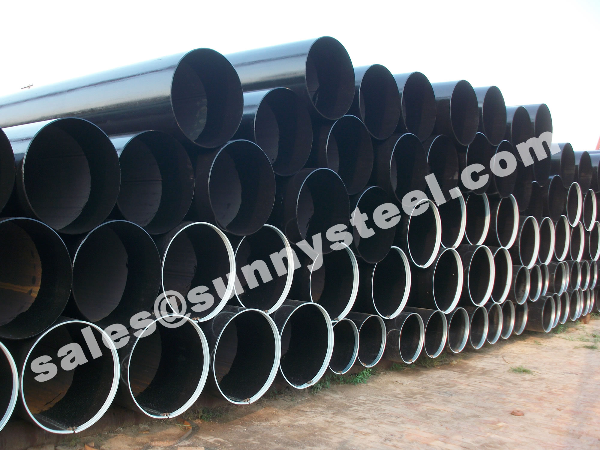
The process begins with the cutting of the strip of the required size on slitting line and then fed through the Tube Mill for formation of line pipe. Once the formation of pipe is done, it is passed through the high frequency welder where the edges are welded together.
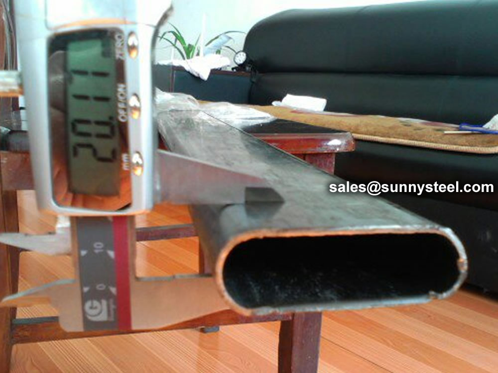
During the process of welding, because of immense generation of heat, there is formation of beads on both the edges, inside and outside the pipes. These beads are then cut in order to have unrestricted flow of fluid/gas inside the pipe.
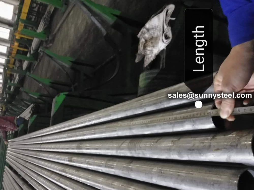
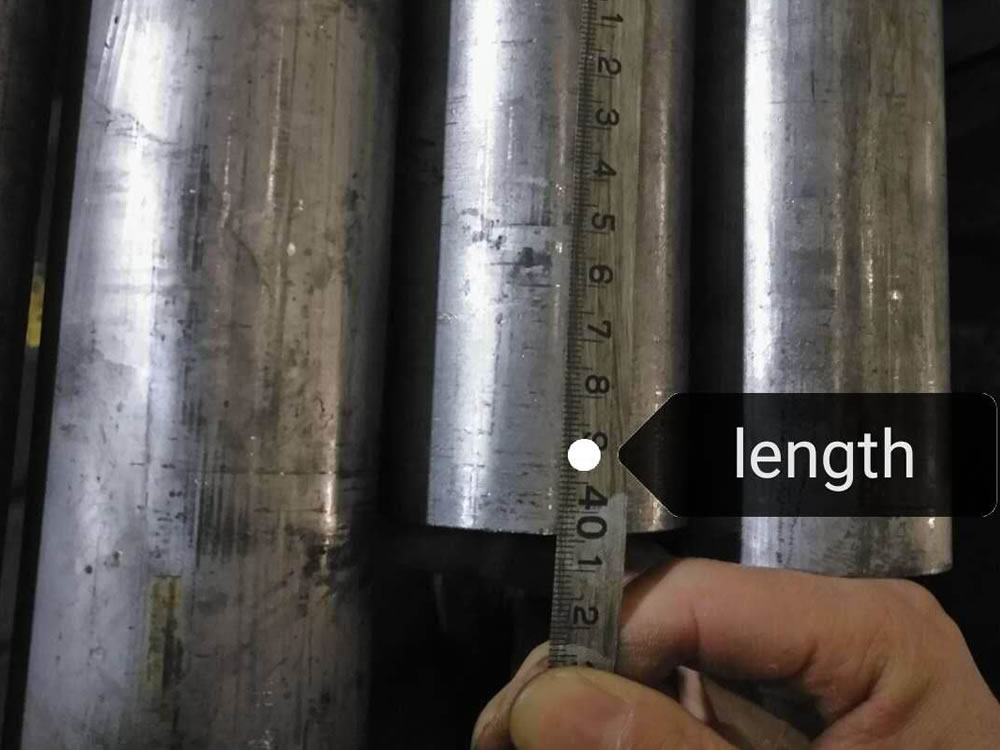
Thereafter, pipes are cut into the required length and are transferred to finishing sections for further processing and testing of the line pipes like straightening, End Chamfering/Facing, Hydro-testing, Non-destructive Testing, Threading, Galvanizing etc., depending on the requirement of the customer.
Using its specialist expertise in high frequency welding, TWI has supported industry with a range of project and consultancy work which has included:
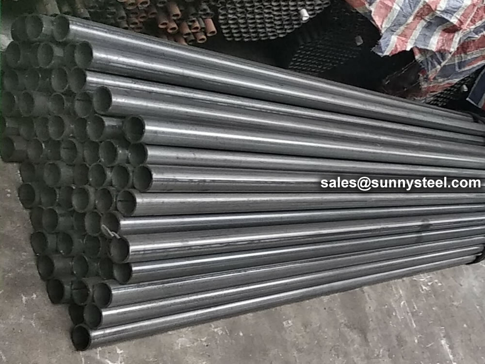
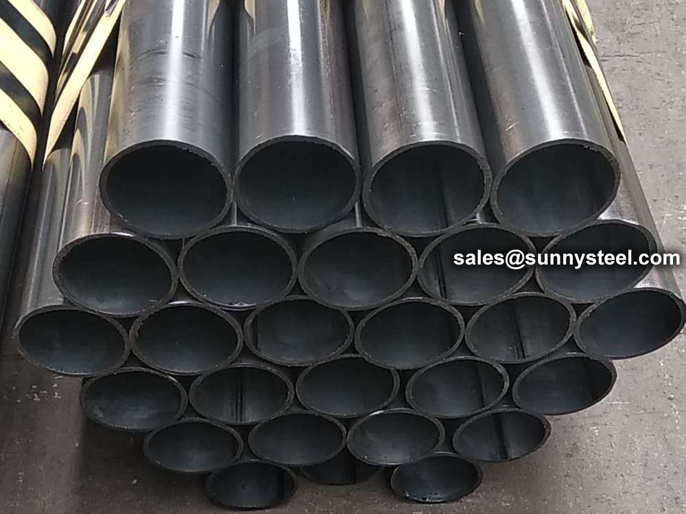
HFW welded steel pipes are widely preferred in Oil, Natural Gas, Water and other liquids transportation and distribution lines, heating, cooling, ventilation piping and steel structures for construction and other general purposes by means of precise production tolerances and high capacity manufacturing method.
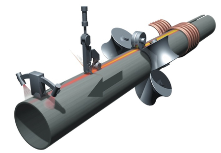
Line Pipe uses High Frequency Induction (HFI) resistance pressure welding for longitudinal welding. The endless strip passes through rolling mills where it is formed into an open tube which passes through a high-frequency inductor consisting of a metal coil with single or multiple windings. This induces a high-frequency ring current in the tube, which closes preferentially at the strip edges, which converge at the welding point. The temperature required for welding is generated by resistance heating a narrow zone along the strip edges.
The heated strip edges are pressed together by pressure rollers, resulting in a homogeneous longitudinal weld without filler material. The flash produced during welding on both the inner and outer surfaces is scraped off to the level of the pipe surface using special tools.
Immediately afterwards, the HFI weld is subjected to a multi-stage inductive annealing treatment to ensure that the properties in the weld area match those of the base material. The continuous tube is then straightened, rolled to size and finally cut to length using a flying saw.
| Product Name | Executive Standard | Dimension (mm) | Steel Code / Steel Grade |
|---|---|---|---|
| Casting | API 5CT | Ø48.3~273 x WT2.77~11.43 | J55, K55, N80, L80 |
| Tubing | API 5CT | Ø48.3~273 x WT2.77~11.43 | J55, K55, N80, L80, H40 |
| Product Name | Executive Standard | Dimension (mm) | Steel Code / Steel Grade |
|---|---|---|---|
| Line Pipes | API 5L | Ø60.3~273.1 x WT2.77~12.7 | A25, A, B, X42, X46, X52, X56, X60, X65, X70, X80 |
| Product Name | Executive Standard | Dimension (mm) | Steel Code / Steel Grade |
|---|---|---|---|
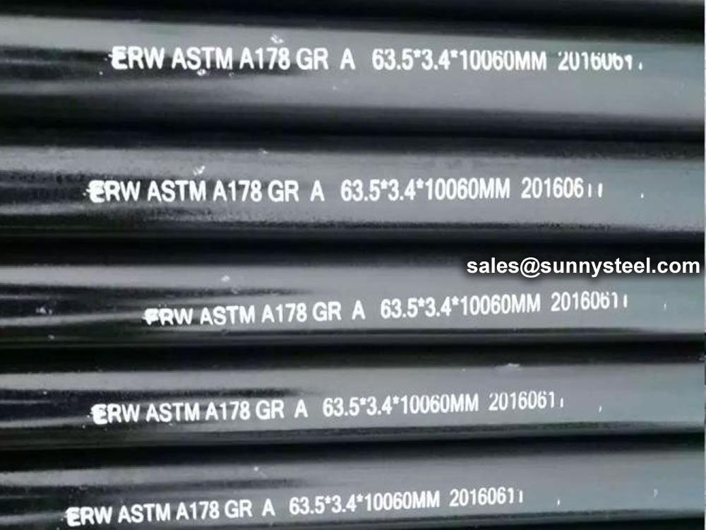
| Electric-Resistance-Welded Steel Pipes | ASTM A135 | Ø42.2~114.3 x WT2.11~2.63 | A |
| Electric-Resistance-Welded Carbon Steel and Carbon-Manganese Steel Boiler and Superheater Tubes | ASTM A178 | 42.2-114.3 x 2.11-2.63 | A, C, D |
| ERW and Hot-dip Galvanized Steel Pipes | ASTM A53 | Ø21.3~273 x WT2.11~12.7 | A, B |
| Pipes for Piling Usage | ASTM A252 | Ø219.1~508 x WT3.6~12.7 | Gr.2, Gr.3 |
| Tubes for General Structural Purpose | ASTM A500 | Ø21.3~273 x WT2.11~12.7 | Gr.2, Gr.3 |
| Square Pipes for General Structural Purpose | ASTM A500 | 25 x 25~160 x 160 x WT1.2~8.0 | Carbon Steel |
| Product Name | Executive Standard | Dimension (mm) | Steel Code / Steel Grade |
|---|---|---|---|
| Threaded Steel Pipes | DIN 2440 | Ø21~164 x WT2.65~4.85 | Carbon Steel |
| Product Name | Executive Standard | Dimension (mm) | Steel Code / Steel Grade |
|---|---|---|---|
| Screwed and Socketed Steel Tubes | BS 1387 | Ø21.4~113.9 x WT2~3.6 | Carbon Steel |
| Scaffolding Pipes | EN 39 | Ø48.3 x WT3.2~4 | Carbon Steel |
| Product Name | Executive Standard | Dimension (mm) | Steel Code / Steel Grade |
|---|---|---|---|
| Carbon Steel Tubes for General Structure Purpose | JIS G3444 | Ø21.7~216.3 x WT2.0~6.0 | Carbon Steel |
| Carbon Steel Tubes for Machine Structure Purpose | JIS G3445 | Ø15~76 x WT0.7~3.0 | STKM11A, STKM13A |
| Carbon Steel Pipes for Ordinary Piping | JIS G3452 | Ø21.9~216.3 x WT2.8~5.8 | Carbon Steel |
| Carbon Steel Pipes for Pressure Service | JIS G3454 | Ø21.7~216.3 x WT2.8~7.1 | Carbon Steel |
| Carbon Steel Rigid Steel Conduits | JIS G8305 | Ø21~113.4 x WT1.2~3.5 | G16~G104, C19~C75, E19~E75 |
| Carbon Steel Rectangular Pipes for General Structure | JIS G3466 | 16 x 16~150 x 150 x WT0.7~6 | Carbon Steel |
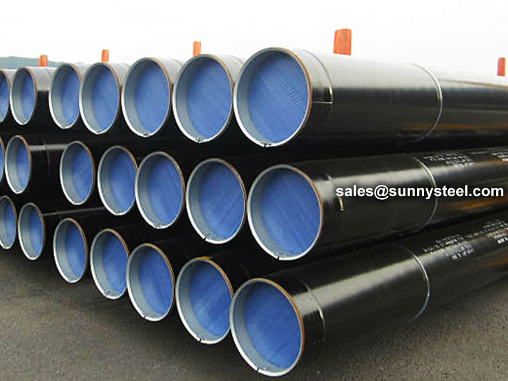
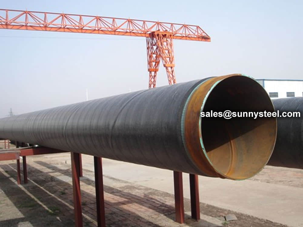
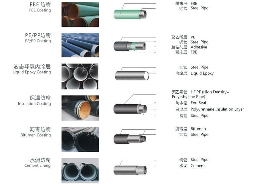
Pipeline coating is the most consistent and successful solution for protecting ERW pipes from corrosion, from moisture, other harmful chemicals.
Anti-corrosion steel pipe is processed through the preservation process, which can effectively prevent or slow down the process in the transport and use of chemical or electrochemical corrosion reaction of steel pipe.
Therefore pipe anti-corrosion layer is an important barrier to prevent soil erosion. A well-known foreign scholar put forward” 3PE france protective layer”, so far, anti-corrosion methods is widely used.
Coated pipes offer high resistance to corrosion on pipes and provide many benefits such as:
The basic principles of urban gas pipeline coating selection:


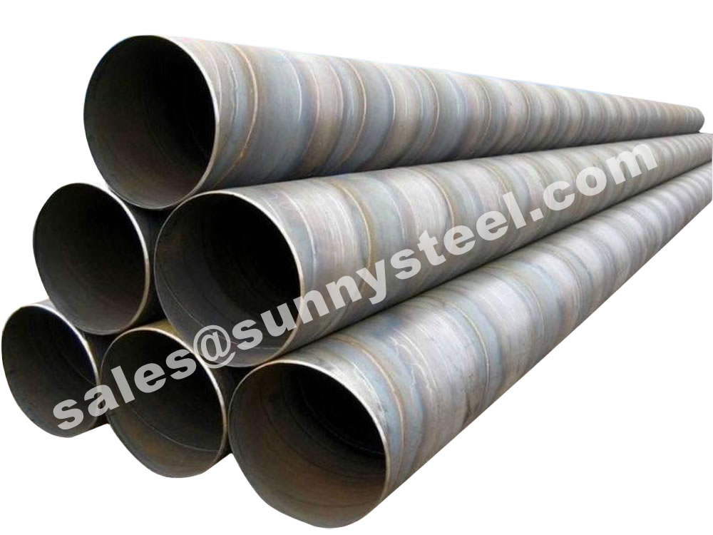
The alloy content of the coil is often lower than similar grades of steel plate, improving the weldability of the spiral welded pipe. Due to the rolling direction of spiral welded pipe coil is not perpendicular to the pipe axis direction, the crack resistance of the spiral welded pipe materials.
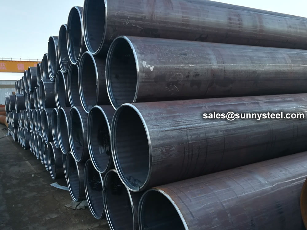
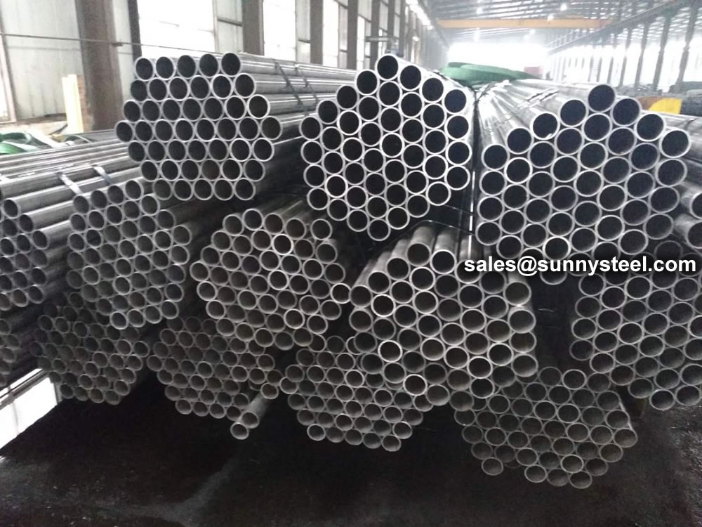
Welded steel pipe refers to a steel pipe with seams on the surface that is welded by bending and deforming a steel strip or steel plate into a circular, square or other shape. The blanks used for welded steel pipes are steel sheets or strips.
Since the 1930s, with the rapid development of continuous rolling production of high-quality strip steel and the advancement of welding and inspection technology, the quality of welds has been continuously improved, and the varieties and specifications of welded steel pipes have been increasing.
When the T-shaped welded steel pipe contains Ni, it has strong corrosion resistance in an acidic environment. In an environment containing sulfuric acid or hydrochloric acid, the higher the Ni content in the T-shaped welded steel pipe, the stronger the corrosion resistance. Under normal circumstances, only adding Cr to the T-shaped welded steel pipe can prevent the phenomenon of corrosion. The poor edge condition of the strip is another important cause of misalignment. The effects of changes in mass flow, heat flow density and structural parameters (ratio of helical curvature diameter to T-shaped welded steel pipe diameter Dc/D) on the heat transfer coefficient of saturated bubble boiling in vertical spiral pipes.
During the production of T-shaped welded steel pipes, misalignment occurs from time to time, and there are many influencing factors. In production practice, the steel pipe is often degraded by the wrong side and out of tolerance. Therefore, it is necessary to analyze the reasons for the misalignment of the spiral steel pipe and its preventive measures.
Due to the poor shape and dimensional accuracy of the head and tail of the uncut steel strip, it is easy to cause the steel strip to bend hard and cause misalignment during butt joint. Simulation parameter range: vertical pipe: pipe diameter D=10mm, pipe length L=660mm; three types of vertical T-shaped welded steel pipe: pipe diameter D=10mm, the change of the ratio of the curvature diameter of the T-shaped welded steel pipe to the spiral pipe diameter is Dc /D=15, 20, 25, helical pitch Pt=20mm, tube lengths are L=503mm, L=660mm, L=817mm respectively. Mass flow G=200~400Kg/(m'2 s), heat flux density q=5~15KW/m'2, saturation pressure p, saturation=0.414880MPa, saturation temperature T, saturation=283.15K.
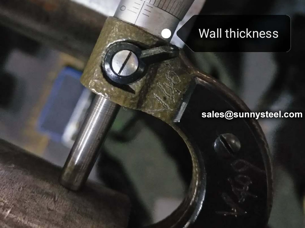
The technical requirements and inspection of welded pipes are based on the provisions of the GB3092 "Welded Steel Pipes for Low-Pressure Fluid Transmission". It can be delivered according to fixed length or double length. The surface of the steel pipe should be smooth, and defects such as folds, cracks, delamination, and lap welding are not allowed. The surface of the steel pipe is allowed to have minor defects such as scratches, scratches, weld misalignment, burns and scars that do not exceed the negative deviation of the wall thickness. The thickening of the wall thickness and the presence of inner seam weld bars are allowed at the weld.
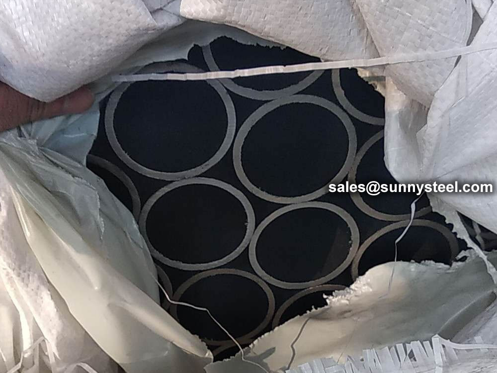
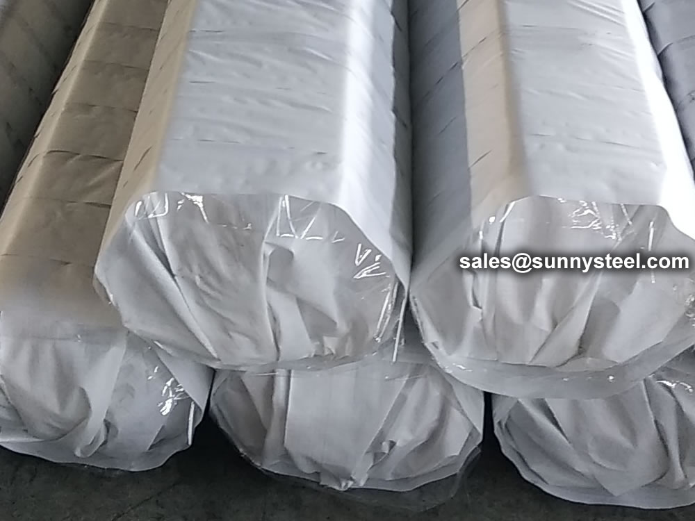
Welded steel pipes should be subjected to mechanical performance test, flattening test and flaring test, and must meet the requirements of the standard. When the steel pipe should be able to withstand the internal pressure, carry out a pressure test of 2.5Mpa, and keep it for one minute without leakage. The method of eddy current flaw detection is allowed to replace the hydrostatic test. The eddy current flaw detection is carried out according to the standard of GB7735 "Steel tube eddy current flaw detection inspection method". The eddy current flaw detection method is to fix the probe on the frame, keep a distance of 3~5mm between the flaw detection and the weld seam, and conduct a comprehensive scan of the weld seam by the rapid movement of the steel pipe. The flaw detection signal is automatically processed and sorted by the eddy current flaw detector. To achieve the purpose of flaw detection. The welded pipe after the flaw detection is cut off according to the specified length with a flying saw, and it is rolled off the assembly line through the turning frame. Both ends of the steel pipe should be chamfered with flat ends, printed with marks, and the finished pipes are packed in hexagonal bundles before leaving the factory.
Straight seam steel pipe is a steel pipe whose weld seam is parallel to the longitudinal direction of the steel pipe. Generally, its strength is higher than that of straight seam welded pipe. Narrower billets can be used to produce welded pipes with larger diameters, and the same width of billets can be used to produce welded pipes with different pipe diameters. But compared with the straight seam pipe of the same length, the weld length is increased by 30~100%, and the production speed is lower. So what are its processing methods?
The surface quenching and tempering heat treatment of straight seam welded pipe is usually carried out by induction heating or flame heating. The main technical parameters are surface hardness, local hardness and effective hardened layer depth. Vickers hardness tester can be used for hardness testing, and Rockwell or superficial Rockwell hardness tester can also be used. When the surface heat treatment hardened layer is thick, the Rockwell hardness tester can also be used. When the thickness of the heat-treated hardened layer is 0.4-0.8mm, the HRA scale can be used, and when the thickness of the hardened layer exceeds 0.8mm, the HRC scale can be used.
If the parts require high local hardness, local quenching heat treatment can be carried out by means of induction heating. Such longitudinal welded pipes usually need to mark the location of local quenching heat treatment and local hardness value on the drawing. Hardness testing of longitudinally welded pipes shall be carried out in the area. The hardness testing instrument can use a Rockwell hardness tester to test the HRC hardness value. If the heat-treated hardened layer is shallow, a surface Rockwell hardness tester can be used to test the HRN hardness value.
The three hardness values of Vickers, Rockwell and Superficial Rockwell can be easily converted to each other and converted into hardness values required by standards, drawings or users. The corresponding conversion tables are given in the international standard ISO, the American standard ASTM and the Chinese standard GB/T.
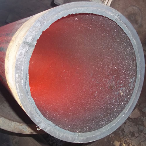
Ceramic lined pipe is made through self-propagating high-temperature synthesis (SHS) technique.
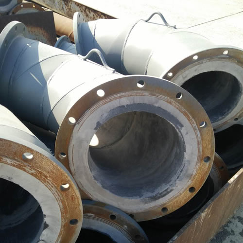
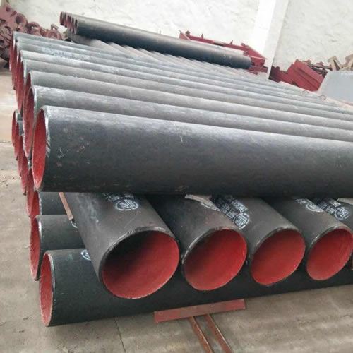
Cast basalt lined steel pipe is composed by lined with cast basalt pipe, outside steel pipe and cement mortar filling between the two layers.
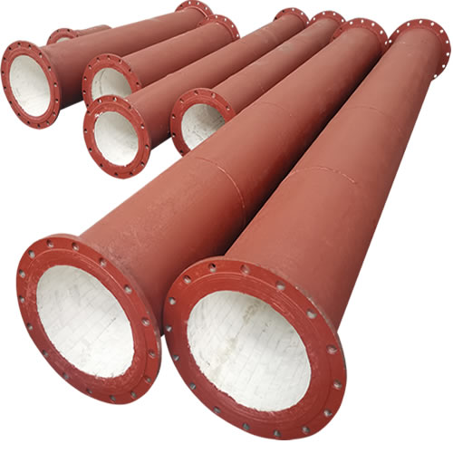
Ceramic tile lined pipes have very uniform coating of specially formulated ceramic material that is affixed to the inner of the pipe.
The material of the rare earth alloy wear-resistant pipe is ZG40CrMnMoNiSiRe, which is also the grade of rare earth alloy steel.
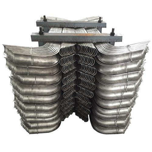
Tubes Erosion Shields are used to protect boiler tubing from the highly erosive effects of high temperatures and pressures thereby greatly extending tube life.
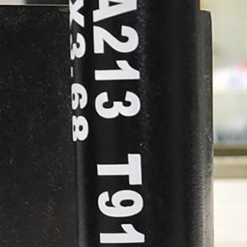
The ASTM A213 T91 seamless tubes are primarily used for boiler, superheater, and heat-exchanger.

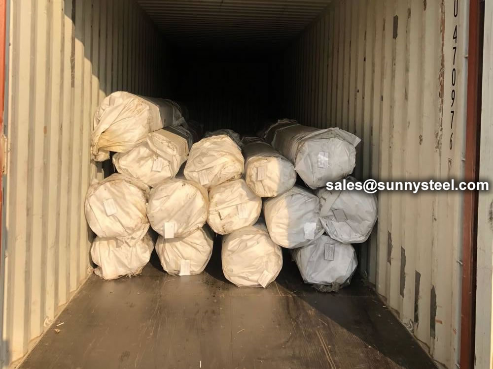
When you partner with Sunny Steel, you can stop worrying about meeting deadlines thanks to our responsive and timely service. You'll also say goodbye to unnecessary shopping around. Instead, you'll get white glove service from an expert who understands your needs and can get you the materials you need quickly.